Lexus ES: Terminals Of Ecu
TERMINALS OF ECU
HYBRID VEHICLE CONTROL ECU
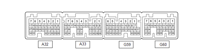
| Terminal No. (Symbol) | Wiring Color | Terminal Description | Input/Output | Condition | Specified Condition |
|---|---|---|---|---|---|
| A32-1 (+B2) - G59-6 (E1) | W - W-B | Power source | Input | Power switch on (IG) | 11 to 14 V |
| A32-3 (IG2) - G59-6 (E1) | B - W-B | Power source | Input | Power switch on (IG) | 11 to 14 V |
| A32-8 (VCP2) - A32-18 (EPA2) | SB - P | Accelerator pedal sensor assembly power source (for VPA2) | Output | Power switch on (IG) | 4.5 to 5.5 V |
| A32-9 (VCPA) - A32-20 (EPA) | BE - L | Accelerator pedal sensor assembly power source (for VPA) | Output | Power switch on (IG) | 4.5 to 5.5 V |
| A32-13 (IWP) - G59-6 (E1) | L - W-B | Inverter water pump assembly signal | Output | Power switch on (READY) | Pulse generation (Waveform 1) |
| A32-14 (NIWP) - G59-6 (E1) | W - W-B | Inverter water pump assembly signal | Input | Power switch on (READY) | Pulse generation (Waveform 1) |
| A32-15 (STP) - G59-6 (E1) | GR - W-B | Stop light switch | Input | Brake pedal depressed | 11 to 14 V |
| Brake pedal released | 0 to 1.5 V | ||||
| A32-17 (LIN3) - G59-6 (E1) | L - W-B | LIN communication signal (A/C inverter, auxiliary battery state sensor) | Input/Output | Power switch on (READY) | Pulse generation |
| A32-21 (TTA) - A32-31 (ETTA) | GR - SB | Transmission fluid temperature sensor | Input | Power switch on (IG), temperature 25°C (77°F) | 3.6 to 4.6 V |
| Power switch on (IG), temperature 60°C (140°F) | 2.2 to 3.2 V | ||||
| A32-22 (ACCI) - G59-6 (E1) | P - W-B | ACC relay | Input | Power switch on (ACC) | 11 to 14 V |
| A32-24 (MMT) - A32-23 (MMTG) | L - Y | Motor temperature sensor | Input | Power switch on (IG), temperature 25°C (77°F) | 3.6 to 4.6 V |
| Power switch on (IG), temperature 60°C (140°F) | 2.2 to 3.2 V | ||||
| A32-26 (GMT) - A32-27 (GMTG) | P - V | Generator temperature sensor | Input | Power switch on (IG), temperature 25°C (77°F) | 3.6 to 4.6 V |
| Power switch on (IG), temperature 60°C (140°F) | 2.2 to 3.2 V | ||||
| A32-28 (VPA2) - A32-18 (EPA2) | GR - P | Accelerator pedal sensor assembly (for accelerator pedal position detection) | Input | Power switch on (IG), accelerator pedal released | 1.0 to 2.2 V |
| Power switch on (IG), engine stopped, shift lever in P, accelerator pedal fully depressed | 3.4 to 5.3 V | ||||
| A32-30 (VPA) - A32-20 (EPA) | G - L | Accelerator pedal sensor assembly (for accelerator pedal position detection) | Input | Power switch on (IG), accelerator pedal released | 0.4 to 1.4 V |
| Power switch on (IG), engine stopped, shift lever in P, accelerator pedal fully depressed | 2.6 to 4.5 V | ||||
| A33-1 (PSFT) - G59-6 (E1) | L - W-B | Shift lever position sensor power source | Output | Power switch on (ACC) | 6.0 to 14 V |
| A33-2 (BL) - G59-6 (E1) | BE - W-B | Back-up light | Output | Power switch on (IG), shift lever in R | 11 to 14 V |
| A33-4 (+B1) - G59-6 (E1) | R - W-B | Power source | Input | Power switch on (IG) | 11 to 14 V |
| A33-6 (MREL) - G59-6 (E1) | G - W-B | Main relay | Output | Power switch on (IG) | 11 to 14 V |
| A33-7 (IGB) - G59-6 (E1) | B - W-B | Power source | Input | Power switch on (IG) | 8.5 to 14 V |
| A33-12 (HSDN) - G59-6 (E1) | W - W-B | MG ECU shutdown signal | Output | Power switch on (READY) | 0 to 1.5 V |
| A33-13 (ILK) - G59-6 (E1) | GR - W-B | Interlock switch | Input | Power switch on (IG), service plug grip installed correctly | 0 to 1.5 V |
| Power switch on (IG), service plug grip not installed | 11 to 14 V | ||||
| A33-14 (DB2) - G59-6 (E1) | V - W-B | Shift lever position signal | Input | Power switch on (IG), shift lever in D or S | 6.0 to 14 V |
| Power switch on (IG), shift lever not in D or S | 0 to 1.5 V | ||||
| A33-15 (R) - G59-6 (E1) | LG - W-B | Shift lever position signal | Input | Power switch on (IG), shift lever in R | 6.0 to 14 V |
| Power switch on (IG), shift lever not in R | 0 to 1.5 V | ||||
| A33-17 (PR) - G59-6 (E1) | R - W-B | Shift lever position signal | Input | Power switch on (IG), shift lever in P or R | 6.0 to 14 V |
| Power switch on (IG), shift lever not in P or R | 0 to 1.5 V | ||||
| A33-20 (N) - G59-6 (E1) | G - W-B | Shift lever position signal | Input | Power switch on (IG), shift lever in N | 6.0 to 14 V |
| Power switch on (IG), shift lever not in N | 0 to 1.5 V | ||||
| A33-21 (P) - G59-6 (E1) | BE - W-B | Shift lever position signal | Input | Power switch on (IG), shift lever in P | 6.0 to 14 V |
| Power switch on (IG), shift lever not in P | 0 to 1.5 V | ||||
| A33-26 (DB1) - G59-6 (E1) | W - W-B | Shift lever position signal | Input | Power switch on (IG), shift lever in D or S | 6.0 to 14 V |
| Power switch on (IG), shift lever not in D or S | 0 to 1.5 V | ||||
| A33-28 (ST1-) - G59-6 (E1) | LG - W-B | Stop light switch signal | Input | Power switch on (IG), brake pedal depressed | 0 to 1.5 V |
| Power switch on (IG), brake pedal released | 11 to 14 V | ||||
| A33-30 (HMCL) - G59-6 (E1) | W - W-B | MG ECU communication request signal | Input/Output | Power switch on (IG) | Pulse generation (Waveform 2) |
| A33-31 (HMCH) - G59-6 (E1) | B - W-B | MG ECU communication request signal | Input/Output | Power switch on (IG) | Pulse generation (Waveform 2) |
| A33-34 (PNB) - G59-6 (E1) | B - W-B | Shift lever position signal | Input | Power switch on (IG), shift lever in P or N | 6.0 to 14 V |
| G59-1 (SMRG) - G59-5 (E01) | G - W-B | System main relay operation signal | Output | Power switch on (IG) → Power switch on (READY) | Pulse generation (Waveform 3) |
| G59-3 (SMRP) - G59-5 (E01) | W - W-B | System main relay operation signal | Output | Power switch on (IG) → Power switch on (READY) | Pulse generation (Waveform 3) |
| G59-4 (SMRB) - G59-5 (E01) | GR - W-B | System main relay operation signal | Output | Power switch on (IG) → Power switch on (READY) | Pulse generation (Waveform 3) |
| G59-5 (E01) - Body ground | W-B - Body ground | Ground | - | Always | Below 1 Ω |
| G59-6 (E1) - Body ground | W-B - Body ground | Ground | - | Always | Below 1 Ω |
| G59-8 (INDR) - G59-6 (E1) | LG - W-B | Shift position indicator signal | Input | Power switch on (IG), shift lever in R | 0 to 3.2 V |
| Power switch on (IG), shift lever not in R | 11 to 14 V | ||||
| G59-9 (ST2) - G59-6 (E1) | L - W-B | Starter signal | Input | Power switch on (IG) | 0 to 1.5 V |
| G59-10 (NORM) - G59-6(E1) | LG - W-B | Drive mode select switch signal | Input | Power switch on (IG), drive mode select switch not pushed | 11 to 14 V |
| Power switch on (IG), drive mode select switch being pushed and held | 0 to 1.5 V | ||||
| G59-32 (BTH+) - G59-6 (E1) | LG - W-B | Communication signal from battery voltage sensor to hybrid vehicle control ECU | Input | Power switch on (IG) | Pulse generation (Waveform 4) |
| G59-33 (BTH-) - G59-6 (E1) | W - W-B | Communication signal from battery voltage sensor to hybrid vehicle control ECU | Input | Power switch on (IG) | Pulse generation (Waveform 4) |
| G60-1 (M) - G59-6 (E1) | B - W-B | Transmission control | Input | Power switch on (IG), shift lever in S | 11 to 14 V |
| Power switch on (IG), shift lever not in S | 0 to 1.5 V | ||||
| G60-3 (BATT) - G59-6 (E1) | L - W-B | Constant power source | Input | Power switch on (IG) | 11 to 14 V |
| Power switch on (READY) | 11 to 15.5 V | ||||
| G60-4 (E12) - Body ground | W-B - Body ground | Ground | - | Always | Below 1 Ω |
| G60-5 (E02) - Body ground | W-B - Body ground | Ground | - | Always | Below 1 Ω |
| G60-6 (SPRT) - G59-6 (E1) | BE - W-B | Drive mode select switch signal | Input | Power switch on (IG), drive mode select switch not turned | 11 to 14 V |
| Power switch on (IG), drive mode switch being turned and held at Sport position | 0 to 1.5 V | ||||
| G60-7 (PLKC) - G59-6 (E1) | L - W-B | Shift lock release request signal | Output | Power switch on (READY), brake pedal depressed | 11 to 14 V |
| Power switch on (READY), brake pedal released | 0 to 1.5 V | ||||
| G60-8 (SFTD) - G59-6 (E1) | W - W-B | Transmission control | Input | Power switch on (IG), shift lever in S | 11 to 14 V |
| Power switch on (IG), shift lever in (-) or shift paddle switch LH (-) operated | 0 to 1.5 V | ||||
| G60-9 (SFTU) - G59-6 (E1) | LG - W-B | Transmission control | Input | Power switch on (IG), shift lever in S | 11 to 14 V |
| Power switch on (IG), shift lever in (+) or shift paddle switch RH (+) operated | 0 to 1.5 V | ||||
| G60-10 (INDM) - G59-6 (E1) | LA-GR - W-B | Shift position indicator signal | Input | Power switch on (IG), shift lever in S | 0 to 3.2 V |
| Power switch on (IG), shift lever not in S | 11 to 14 V | ||||
| G60-11 (INDD) - G59-6 (E1) | W - W-B | Shift position indicator signal | Input | Power switch on (IG), shift lever in D | 0 to 3.2 V |
| Power switch on (IG), shift lever not in D | 11 to 14 V | ||||
| G60-12 (INDN) - G59-6 (E1) | R - W-B | Shift position indicator signal | Input | Power switch on (IG), shift lever in N | 0 to 3.2 V |
| Power switch on (IG), shift lever not in N | 11 to 14 V | ||||
| G60-13 (INDP) - G59-6 (E1) | B - W-B | Shift position indicator signal | Input | Power switch on (IG), shift lever in P | 0 to 3.2 V |
| Power switch on (IG), shift lever not in P | 11 to 14 V | ||||
| G60-14 (ABFS) - G59-6 (E1) | B - W-B | Airbag activation signal | Input | Power switch on (READY) | Pulse generation (Waveform 5) |
| G60-15 (EVSW) - G59-6 (E1) | G - W-B | Drive mode select switch signal | Input | Power switch on (IG), EV mode switch not pushed | 11 to 14 V |
| Power switch on (IG), EV mode switch being pushed and held | 0 to 1.5 V | ||||
| G60-24 (CA1L) - G59-6 (E1) | W - W-B | CAN communication signal | Input/Output | Power switch on (IG) | Pulse generation (Waveform 6) |
| G60-25 (CA1H) - G59-6 (E1) | L - W-B | CAN communication signal | Input/Output | Power switch on (IG) | Pulse generation (Waveform 6) |
| G60-29 (SI0) - G59-6 (E1) | SB - W-B | HV battery cooling blower assembly operation signal | Output | Cooling fans operating | Pulse generation (Waveform 7) |
| Cooling fans not operating | 4.5 to 5.5 V | ||||
| G60-30 (CA3N) - G59-6 (E1) | W - W-B | CAN communication signal | Input/Output | Power switch on (IG) | Pulse generation (Waveform 8) |
| G60-31 (CA3P) - G59-6 (E1) | G - W-B | CAN communication signal | Input/Output | Power switch on (IG) | Pulse generation (Waveform 8) |
(a) Oscilloscope waveforms
HINT:
Oscilloscope waveform samples are provided here for informational purposes. Noise and fluttering waveforms have been omitted.
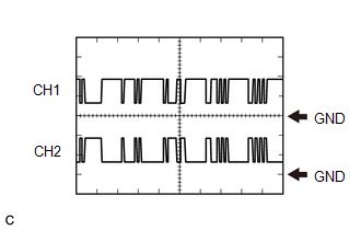
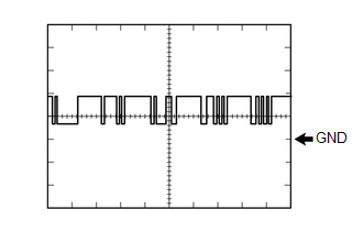
(1) Waveform 1 (Inverter water pump assembly signal)
| Item | Content |
|---|---|
| Terminal | CH1: A32-13 (IWP) - G59-6 (E1) CH2: A32-14 (NIWP) - G59-6 (E1) |
| Equipment Setting | 5 V/DIV., 20 ms./DIV. |
| Condition | Power switch on (READY) |
.png)
HINT:
The duty of the IWP signal and the frequency of the NIWP signal change according to the coolant (for inverter) temperature.
(2) Waveform 2 (MG ECU communication request signal)
| Item | Content |
|---|---|
| Terminal | CH1: A33-31 (HMCH) - G59-6 (E1) CH2: A33-30 (HMCL) - G59-6 (E1) |
| Equipment Setting | 1 V/DIV., 50 μs./DIV. |
| Condition | Power switch on (IG) |
HINT:
The waveform will vary depending on the content of the digital communication (digital signal).
.png)
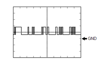
(3) Waveform 3 (System main relay operation signal)
| Item | Content |
|---|---|
| Terminal | CH1: G59-3 (SMRP) - G59-5 (E01) CH2: G59-4 (SMRB) - G59-5 (E01) CH3: G59-1 (SMRG) - G59-5 (E01) |
| Equipment Setting | 10 V/DIV., 200 ms./DIV. |
| Condition | Power switch on (IG) → Power switch on (READY) |
.png)
(4) Waveform 4 (Communication signal from battery voltage sensor to hybrid vehicle control ECU)
| Item | Content |
|---|---|
| Terminal | CH1: G59-32 (BTH+) - G59-6 (E1) CH2: G59-33 (BTH-) - G59-6 (E1) |
| Equipment Setting | 2 V/DIV., 500 μs./DIV. |
| Condition | Power switch on (IG) |
HINT:
The waveform will vary depending on the content of the digital communication (digital signal).
(5) Waveform 5 (Airbag activation signal)
| Item | Content |
|---|---|
| Terminal | G60-14 (ABFS) - G59-6 (E1) |
| Equipment Setting | 5 V/DIV., 150 ms./DIV. |
| Condition | Power switch on (READY) |
.png)
(6) Waveform 6 (CAN communication signal)
| Item | Content |
|---|---|
| Terminal | CH1: G60-25 (CA1H) - G59-6 (E1) CH2: G60-24 (CA1L) - G59-6 (E1) |
| Equipment Setting | 1 V/DIV., 50 μs./DIV. |
| Condition | Power switch on (IG) |
HINT:
The waveform will vary depending on the content of the digital communication (digital signal).
.png)
(7) Waveform 7 (HV battery blower fan operation signal)
| Item | Content |
|---|---|
| Terminal | G60-29 (SI0) - G59-6 (E1) |
| Equipment Setting | 10 V/DIV., 1 ms./DIV. |
| Condition | Cooling fans operating |
HINT:
The waveform will vary with the operating speed of the battery cooling blower assembly.
(8) Waveform 8 (CAN communication signal)
| Item | Content |
|---|---|
| Terminal | CH1: G60-31 (CA3P) - G59-6 (E1) CH2: G60-30 (CA3N) - G59-6 (E1) |
| Equipment Setting | 1 V/DIV., 50 μs./DIV. |
| Condition | Power switch on (IG) |
HINT:
The waveform will vary depending on the content of the digital communication (digital signal).
.png)
BATTERY VOLTAGE SENSOR
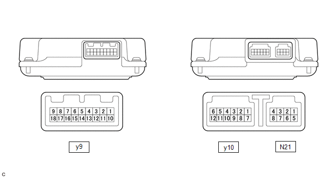
| Terminal No. (Symbol) | Wiring Color | Input/Output | Terminal Description | Condition | Specified Condition |
|---|---|---|---|---|---|
| y10-1 (TC0) - y10-7 (GC0) | G - G | IN | Intake air temperature sensor | Power switch on (IG), HV battery intake air temperature: -40 to 90°C (-40 to 194°F) | 4.8 (-40°C (-40°F)) to 1.0 V (90°C (194°F)) |
| y10-2 (TB2) - y10-8 (GB2) | R - R | IN | Battery temperature sensor 2 | Power switch on (IG), HV battery temperature: -40 to 90°C (-40 to 194°F) | 4.8 (-40°C (-40°F)) to 1.0 V (90°C (194°F)) |
| y10-3 (TB1) - y10-9 (GB1) | W - W | IN | Battery temperature sensor 1 | Power switch on (IG), HV battery temperature: -40 to 90°C (-40 to 194°F) | 4.8 (-40°C (-40°F)) to 1.0 V (90°C (194°F)) |
| y10-4 (TB0) - y10-10 (GB0) | L - L | IN | Battery temperature sensor 0 | Power switch on (IG), HV battery temperature: -40 to 90°C (-40 to 194°F) | 4.8 (-40°C (-40°F)) to 1.0 V (90°C (194°F)) |
| y10-5 (IB0) - y10-12 (GIB) | Y - B | IN | Battery current sensor | Power switch on (IG) | 0.5 to 4.5 V |
| y10-6 (VIB) - y10-12 (GIB) | BR - B | OUT | Power source for battery current sensor | Power switch on (IG) | 4.5 to 5.5 V |
| N21-1 (IGCT) - N21-5 (GND) | B - W-B | IN | Control signal | Power switch on (IG) | 11 to 14 V |
| N21-2 (BTH+) - N21-5 (GND) | GR - W-B | OUT | Serial communication | Power switch on (IG) | Pulse generation (waveform 1) |
| N21-3 (BTH-) - N21-5 (GND) | W - W-B | OUT | Serial communication | Power switch on (IG) | Pulse generation (waveform 2) |
| N21-5 (GND) - Body ground | W-B | - | Ground | Always (continuity check) | Below 1 Ω |
| N21-8 (FP0) - N21-5 (GND) | B - W-B | IN | Battery cooling blower monitor signal | Battery cooling blower assembly stopped | 0 Hz |
| Battery cooling blower assembly operating (Active Test of cooling fan being performed) | Pulse generation (waveform 3) |
(a) Oscilloscope waveforms
HINT:
Oscilloscope waveform samples are provided here for informational purposes. Noise and fluttering waveforms have been omitted.
(1) Waveform 1 (Serial communication)
| Item | Content |
|---|---|
| Terminal | N21-2 (BTH+) - N21-5 (GND) |
| Equipment Setting | 2 V/DIV., 500 μs/DIV. |
| Condition | Power switch on (IG) |
HINT:
The waveform will vary depending on the content of the digital communication (digital signal).
(2) Waveform 2 (Serial communication)
| Item | Content |
|---|---|
| Terminal | N21-3 (BTH-) - N21-5 (GND) |
| Equipment Setting | 2 V/DIV., 500 μs/DIV. |
| Condition | Power switch on (IG) |
HINT:
The waveform will vary depending on the content of the digital communication (digital signal).
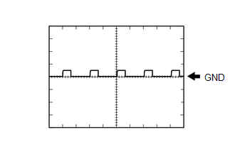
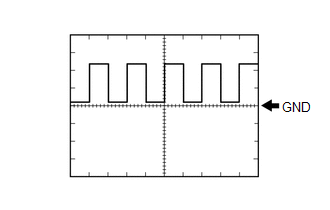
(3) Waveform 3 (Battery cooling blower monitor signal)
| Item | Content |
|---|---|
| Terminal | N21-8 (FP0) - N21-5 (GND) |
| Equipment Setting | 2 V/DIV., 2 ms/DIV. |
| Condition | Battery cooling blower assembly operating (Active Test of cooling fan being performed) |
HINT:
The frequency of the waveform will vary with the operating speed of the battery cooling blower assembly.
READ NEXT:
 Diagnosis System
DIAGNOSIS SYSTEM DESCRIPTION (a) The hybrid vehicle control ECU has a self-diagnosis system. If the computer, hybrid control system, or a component is not working properly, the ECU records the conditi
Dtc Check / Clear
DTC CHECK / CLEAR CHECK FOR DTCS (a) Connect the Techstream to the DLC3. (b) Turn the power switch on (IG). (c) Turn the Techstream on. (d) Enter the following menus: Powertrain / Hybrid Control / Tro
Freeze Frame Data
FREEZE FRAME DATA FREEZE FRAME DATA HINT: The hybrid vehicle control ECU records vehicle and driving condition information as freeze frame data the moment a DTC is stored. It can be used for estimatin
SEE MORE:
Components
COMPONENTS ILLUSTRATION *1 BATTERY SERVICE HOLE COVER *2 SERVICE PLUG GRIP ILLUSTRATION *1 CONNECTOR COVER ASSEMBLY *2 ENGINE ROOM MAIN WIRE Tightening torque for "Major areas involving basic vehicle performance such as moving/turning/stopping": N*m (kgf*cm, ft.*lbf)
Dtc Check / Clear
DTC CHECK / CLEAR CHECK FOR DTC (MAIN BODY) (a) Connect the Techstream to the DLC3. (b) Turn the power switch on (IG). (c) Turn the Techstream on. (d) Enter the following menus: Body Electrical / Main Body / Trouble Codes. Body Electrical > Main Body > Trouble Codes (e) Check for DTCs. CHECK F
