Lexus ES: Fuel Pump "A" Control Circuit Short to Ground or Open (P062714)
DESCRIPTION
Refer to DTC P062712.
Click here .gif)
| DTC No. | Detection Item | DTC Detection Condition | Trouble Area | MIL | Memory | Note |
|---|---|---|---|---|---|---|
| P062714 | Fuel Pump "A" Control Circuit Short to Ground or Open | When the fuel pump control ECU operation duty ratio is 3 to 65%, the FPC terminal voltage is a certain value or less for 3 seconds or more (1 trip detection logic). |
| Comes on | DTC stored | SAE Code: P0628 |
| DTC No. | Data List |
|---|---|
| P062714 | Fuel Pump Control Duty Ratio |
MONITOR DESCRIPTION
The ECM monitors the fuel pump control ECU operation signals.
When the output duty ratio of the operation signal from the ECM is 3 to 65% and the FPC terminal voltage is a certain value or less for 3 seconds or more, the ECM stores a DTC.
MONITOR STRATEGY
| Related DTCs | P0628: Fuel pump control circuit range check (low voltage) |
| Required Sensors/Components (Main) | Fuel pump control ECU |
| Required Sensors/Components (Related) | - |
| Frequency of Operation | Continuous |
| Duration | 3 seconds |
| MIL Operation | Immediate |
| Sequence of Operation | None |
TYPICAL ENABLING CONDITIONS
| Monitor runs whenever the following DTCs are not stored | None |
| All of the following conditions are met | - |
| Output duty cycle | 3 to 65% |
| Auxiliary battery voltage | 10.5 V or higher |
| Power switch | On (IG) |
TYPICAL MALFUNCTION THRESHOLDS
| Fuel pump control module terminal voltage level | Low for 1.163264 seconds or more |
CONFIRMATION DRIVING PATTERN
HINT:
-
After repair has been completed, clear the DTC and then check that the vehicle has returned to normal by performing the following All Readiness check procedure.
Click here
-
When clearing the permanent DTCs, refer to the "CLEAR PERMANENT DTC" procedure.
Click here
- Connect the Techstream to the DLC3.
- Turn the power switch on (IG).
- Turn the Techstream on.
- Clear the DTCs (even if no DTCs are stored, perform the clear DTC procedure).
- Turn the power switch off and wait for at least 30 seconds.
- Turn the power switch on (IG).
- Turn the Techstream on.
-
Put the engine in Inspection Mode (Maintenance Mode).
Click here
- Start the engine and wait 10 seconds or more [A].
- Enter the following menus: Powertrain / Engine / Trouble Codes [B].
-
Read the pending DTCs.
HINT:
- If a pending DTC is output, the system is malfunctioning.
- If a pending DTC is not output, perform the following procedure.
- Enter the following menus: Powertrain / Engine / Utility / All Readiness.
- Input the DTC: P062714.
-
Check the DTC judgment result.
Techstream Display
Description
NORMAL
- DTC judgment completed
- System normal
ABNORMAL
- DTC judgment completed
- System abnormal
INCOMPLETE
- DTC judgment not completed
- Perform driving pattern after confirming DTC enabling conditions
HINT:
- If the judgment result is NORMAL, the system is normal.
- If the judgment result is ABNORMAL, the system is malfunctioning.
- If the judgment result is INCOMPLETE, run the engine at an engine speed of 2500 rpm or more for 10 seconds or more and check the DTC judgment result again.
-
[A] to [B]: Normal judgment procedure.
The normal judgment procedure is used to complete DTC judgment and also used when clearing permanent DTCs.
- When clearing the permanent DTCs, do not disconnect the cable from the auxiliary battery terminal or attempt to clear the DTCs during this procedure, as doing so will clear the universal trip and normal judgment histories.
WIRING DIAGRAM
Refer to DTC P062712.
Click here
CAUTION / NOTICE / HINT
NOTICE:
- Inspect the fuses for circuits related to this system before performing the following procedure.
-
Vehicle Control History may be stored in the hybrid vehicle control ECU assembly if the engine is malfunctioning. Certain vehicle condition information is recorded when Vehicle Control History is stored. Reading the vehicle conditions recorded in both the Freeze Frame Data and Vehicle Control History can be useful for troubleshooting.
Click here
(Select Powertrain in Health Check and then check the time stamp data.)
Click here
-
If any "Engine Malfunction" Vehicle Control History item has been stored in the hybrid vehicle control ECU assembly, make sure to clear it. However, as all Vehicle Control History items are cleared simultaneously, if any Vehicle Control History items other than "Engine Malfunction" are stored, make sure to perform any troubleshooting for them before clearing Vehicle Control History.
Click here
HINT:
Read Freeze Frame Data using the Techstream. The ECM records vehicle and driving condition information as Freeze Frame Data the moment a DTC is stored. When troubleshooting, Freeze Frame Data can help determine if the vehicle was moving or stationary, if the engine was warmed up or not, if the air fuel ratio was lean or rich, and other data from the time the malfunction occurred.
PROCEDURE
| 1. | CHECK HARNESS AND CONNECTOR (POWER SOURCE OF FUEL PUMP CONTROL ECU) |
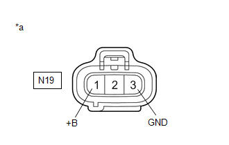
| *a | Front view of wire harness connector (to Fuel Pump Control ECU) |
(a) Disconnect the fuel pump control ECU connector.
(b) Turn the power switch on (IG).
(c) Measure the voltage according to the value(s) in the table below.
Standard Voltage:
| Tester Connection | Condition | Specified Condition |
|---|---|---|
| N19-1 (+B) - N19-3 (GND) | Power switch on (IG) | 11 to 14 V |
| NG | .gif) | GO TO STEP 4 |
|
.gif)
| 2. | INSPECT ECM (FPC TERMINAL) |
.png)
| *a | Front view of wire harness connector (to Fuel Pump Control ECU) |
(a) Disconnect the fuel pump control ECU connector.
(b) Connect the Techstream to the DLC3.
(c) Turn the power switch on (IG).
(d) Turn the Techstream on.
(e) Enter the following menus: Powertrain / Engine / Active Test / Fuel Pump Single Phase Energization.
Powertrain > Engine > Active Test| Tester Display |
|---|
| Fuel Pump Single Phase Energization |
(f) Operate the fuel pump control ECU using the Active Test function and measure the resistance according to the value(s) in the table below.
Standard Resistance:
| Tester Connection | Techstream Operation | Specified Condition |
|---|---|---|
| N19-2 (FPC) - Body ground | Before Active Test → During Active Test | Before Active Test: Resistance is stable → During Active Test: Resistance fluctuates* |
HINT:
*: Using the Active Test, duty control of the transistors in the ECM will be performed. Due to the duty control, resistance of the FPC terminal will be unstable during the Active Test. If the resistance is stable before the Active Test and fluctuates while performing the Active Test, it can be determined that the transistor is operating. If the transistor does not operate during the Active Test, the ECM may be malfunctioning.
| OK | | REPLACE FUEL PUMP CONTROL ECU |
|
| 3. | CHECK HARNESS AND CONNECTOR (FUEL PUMP CONTROL ECU - ECM) |
(a) Disconnect the fuel pump control ECU connector.
(b) Disconnect the ECM connector.
(c) Measure the resistance according to the value(s) in the table below.
Standard Resistance:
| Tester Connection | Condition | Specified Condition |
|---|---|---|
| N19-2 (FPC) - A26-6 (FPC) | Always | Below 1 Ω |
| N19-2 (FPC) or A26-6 (FPC) - Body ground | Always | 10 kΩ or higher |
| OK | | REPLACE ECM |
| NG | | REPAIR OR REPLACE HARNESS OR CONNECTOR |
| 4. | CHECK HARNESS AND CONNECTOR (FUEL PUMP CONTROL ECU - BODY GROUND) |
(a) Disconnect the fuel pump control ECU connector.
(b) Measure the resistance according to the value(s) in the table below.
Standard Resistance:
| Tester Connection | Condition | Specified Condition |
|---|---|---|
| N19-3 (GND) - Body ground | Always | Below 1 Ω |
| NG | | REPAIR OR REPLACE HARNESS OR CONNECTOR |
|
| 5. | INSPECT EFI-MAIN NO. 2 RELAY |
(a) Inspect the EFI-MAIN NO. 2 relay.
Click here
| NG | | REPLACE EFI-MAIN NO. 2 RELAY |
|
| 6. | CHECK TERMINAL VOLTAGE (POWER SOURCE OF EFI-MAIN NO. 2 RELAY) |
.png)
| *1 | No. 1 Engine Room Relay Block and No. 1 Junction Block Assembly |
| *2 | EFI-MAIN NO. 2 Relay |
(a) Remove the EFI-MAIN NO. 2 relay from the No. 1 engine room relay block and No. 1 junction block assembly.
(b) Measure the voltage according to the value(s) in the table below.
Standard Voltage:
| Tester Connection | Condition | Specified Condition |
|---|---|---|
| 3 (EFI-MAIN NO. 2 relay) - Body ground | Always | 11 to 14 V |
| NG | | REPAIR OR REPLACE HARNESS OR CONNECTOR (AUXILIARY BATTERY - EFI-MAIN NO. 2 RELAY) |
|
| 7. | CHECK HARNESS AND CONNECTOR (EFI-MAIN NO. 2 RELAY - BODY GROUND) |
(a) Remove the EFI-MAIN NO. 2 relay from the No. 1 engine room relay block and No. 1 junction block assembly.
(b) Measure the resistance according to the value(s) in the table below.
Standard Resistance:
| Tester Connection | Condition | Specified Condition |
|---|---|---|
| 1 (EFI-MAIN NO. 2 relay) - Body ground | Always | Below 1 Ω |
| NG | | REPAIR OR REPLACE HARNESS OR CONNECTOR |
|
| 8. | CHECK HARNESS AND CONNECTOR (FUEL PUMP CONTROL ECU - EFI-MAIN NO. 2 RELAY) |
(a) Disconnect the fuel pump control ECU connector.
(b) Remove the EFI-MAIN NO. 2 relay from the No. 1 engine room relay block and No. 1 junction block assembly.
(c) Measure the resistance according to the value(s) in the table below.
Standard Resistance:
| Tester Connection | Condition | Specified Condition |
|---|---|---|
| N19-1 (+B) - 5 (EFI-MAIN NO. 2 relay) | Always | Below 1 Ω |
| N19-1 (+B) or 5 (EFI-MAIN NO. 2 relay) - Body ground and other terminals | Always | 10 kΩ or higher |
| OK | | REPAIR OR REPLACE HARNESS OR CONNECTOR (EFI-MAIN NO. 1 RELAY - EFI-MAIN NO. 2 RELAY) |
| NG | | REPAIR OR REPLACE HARNESS OR CONNECTOR |
READ NEXT:
 Internal Control Module EEPROM Data Memory Failure (P062F44)
DESCRIPTION The ECM monitors its internal operation and stores this DTC when it detects an internal malfunction. DTC No. Detection Item DTC Detection Condition Trouble Area MIL Memory N
VIN Not Programmed (P063051)
MONITOR DESCRIPTION DTC P063051 is stored when the Vehicle Identification Number (VIN) is not stored in the ECM or the stored VIN is not accurate. DTC No. Detection Item DTC Detection Condition
Fuel Pump Control Module Internal Electronic Failure (P064A49)
MONITOR DESCRIPTION The fuel pump control ECU has a self-diagnosis function. If there is an internal malfunction, the fuel pump control ECU sends a malfunction signal to the ECM via the FPC drive circ
SEE MORE:
Removal
REMOVAL CAUTION / NOTICE / HINT HINT:
Use the same procedure for the RH side and LH side.
The following procedure is for the LH side.
PROCEDURE 1. REMOVE WASHER NOZZLE SUB-ASSEMBLY (a) Using a screwdriver with its tip wrapped with protective tape, disengage the 2 claws as shown in the illust
CAN Communication Failure (Message Registry) (U1000)
DESCRIPTION The headlight ECU sub-assembly LH or headlight ECU sub-assembly RH stores this DTC if it detects an internal malfunction related to the CAN communication system. for LED Type Turn Signal Light DTC No. Detection Item DTC Detection Condition Trouble Area DTC Output from U100
