Lexus ES: Brake Hold Standby Indicator Light Circuit
DESCRIPTION
The brake hold standby indicator light turns on if brake hold control is possible when the following conditions required for operation standby are met and the brake hold switch (No. 3 combination switch assembly) is pressed while the engine switch on (IG).
-
Conditions required for operation standby:
- The driver door is closed.
- The driver seat belt is fastened.
- The system is normal.
HINT:
If a malfunction occurs in one of the following systems, the brake hold operated indicator light will blink. If this occurs, perform troubleshooting on the malfunctioning system.
- Brake system
- Electric parking brake system
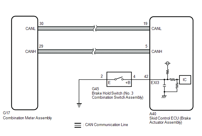
WIRING DIAGRAM
CAUTION / NOTICE / HINT
NOTICE:
After replacing the skid control ECU (brake actuator assembly), perform acceleration sensor zero point calibration and store system information memorization.
Click here .gif)
PROCEDURE
| 1. | PRE-CHECK |
(a) If the brake hold standby indicator light does not illuminate even though the brake hold switch (No. 3 combination switch assembly) is pushed, check that the brake hold function operation conditions are met.
- The driver door is closed.
- The driver seat belt is fastened.
- The system is normal.
HINT:
If a malfunction occurs in one of the following systems, the brake hold operated indicator light will blink. If this occurs, perform troubleshooting on the malfunctioning system.
- Brake system
- Electric parking brake system
|

| 2. | READ VALUE USING TECHSTREAM (BRAKE HOLD READY) |
(a) Connect the Techstream to the DLC3.
(b) Turn the engine switch on (IG).
(c) Enter the following menus: Chassis / Brake/EPB / Data List.
Chassis > Brake/EPB > Data List| Tester Display | Measurement Item | Range | Normal Condition | Diagnostic Note |
|---|---|---|---|---|
| Brake Hold Ready | Brake hold control permission status | Not in stand-by mode / Stand-by mode | Not in stand-by mode: Brake hold function not operating (brake hold indicator not illuminated) Stand-by mode: Brake hold function stand-by state (brake hold indicator illuminated) | - |
| Tester Display |
|---|
| Brake Hold Ready |
(d) All of the following brake hold operation conditions are met:
- The driver door is closed.
- The driver seat belt is fastened.
(e) Check the brake hold standby indicator light and mode condition on the Techstream changes according to brake hold switch (No. 3 combination switch assembly) operation.
Standard:
| Brake Hold Switch (No. 3 Combination Switch Assembly) Operation | Mode Condition Display | Brake Hold Standby Indicator Light |
|---|---|---|
| Not pressed | Not in stand-by mode | Does not come on |
| Pressing the brake hold switch (No. 3 combination switch assembly) | Stand-by mode | come on |
| Result | Proceed to |
|---|---|
| Indicator light and mode condition display do not change | A |
| Mode condition display is normal, but indicator light does not change | B |
| Indicator light and mode condition display are normal | C |
| B |  | INSPECT METER / GAUGE SYSTEM |
| C | | USE SIMULATION METHOD TO CHECK |
|
| 3. | INSPECT NO. 3 COMBINATION SWITCH ASSEMBLY |
| (a) Make sure that there is no looseness at the locking part and the connecting part of the connector. OK: The connector is securely connected. |
|
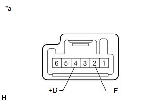
(b) Disconnect the G45 brake hold switch (No. 3 combination switch assembly) connector.
(c) Check both the connector case and the terminal for deformation and corrosion.
OK:
No deformation or corrosion.
(d) Measure the resistance according to the value(s) in the table below.
Standard Resistance:
| Tester Connection | Condition | Specified Condition |
|---|---|---|
| 4 (+B) - 2 (E) | Switch pushed | Below 1 Ω |
| 4 (+B) - 2 (E) | Switch not pushed | 10 kΩ or higher |
| NG | | REPLACE NO. 3 COMBINATION SWITCH ASSEMBLY |
|
| 4. | CHECK HARNESS AND CONNECTOR (NO. 3 COMBINATION SWITCH ASSEMBLY - BRAKE ACTUATOR ASSEMBLY) |
(a) Make sure that there is no looseness at the locking part and the connecting part of the connector.
OK:
The connector is securely connected.
(b) Disconnect the A40 skid control ECU (brake actuator assembly) connector.
(c) Disconnect the G45 brake hold switch (No. 3 combination switch assembly) connector.
(d) Check both the connector case and the terminal for deformation and corrosion.
OK:
No deformation or corrosion.
(e) Measure the resistance according to the value(s) in the table below.
Standard Resistance:
| Tester Connection | Condition | Specified Condition |
|---|---|---|
| G45-4 (+B) - A40-42 (EXI3) | Always | Below 1 Ω |
| G45-4 (+B) or A40-42 (EXI3) - Body ground | Always | 10 kΩ or higher |
| G45-2 (E) - Body ground | Always | Below 1 Ω |
| OK | | REPLACE BRAKE ACTUATOR ASSEMBLY |
| NG | | REPAIR OR REPLACE HARNESS OR CONNECTOR |
READ NEXT:
 Brake Warning Light does not Come ON
DESCRIPTION The skid control ECU (brake actuator assembly) controls the brake warning light / red (malfunction) in the combination meter assembly via CAN communication. CAUTION / NOTICE / HINT NOTICE:
Brake Warning Light Remains ON
DESCRIPTION This procedure is for troubleshooting when the brake warning light / red (malfunction) remains on but no DTCs are output. The skid control ECU (brake actuator assembly) controls the brake
Left Front Wheel ABS Hold Solenoid Control Circuit Short to Battery (C12A512,...,C12B049)
DESCRIPTION The ABS solenoid relay and solenoid valves are built into the brake actuator assembly. The front solenoid valve LH controls the brake fluid pressure of the front wheel cylinder LH of the v
SEE MORE:
Torque Converter Clutch Actuator Stuck On (P07407E)
DESCRIPTION The ECM uses signals from the throttle position sensor, mass air flow meter, transmission revolution sensor (NT), transmission revolution sensor (NC) and crankshaft position sensor to help determine the engagement timing of the lock-up clutch. The ECM monitors the engagement of the clutc
Components
COMPONENTS ILLUSTRATION *1 REAR DRIVE SHAFT OIL SEAL LH - - ● Non-reusable part MP grease
