Lexus ES: System Diagram
Lexus ES (XZ10) Service Manual / Vehicle Exterior / Door / Hatch / Power Trunk Lid System (for Hv Model) / System Diagram
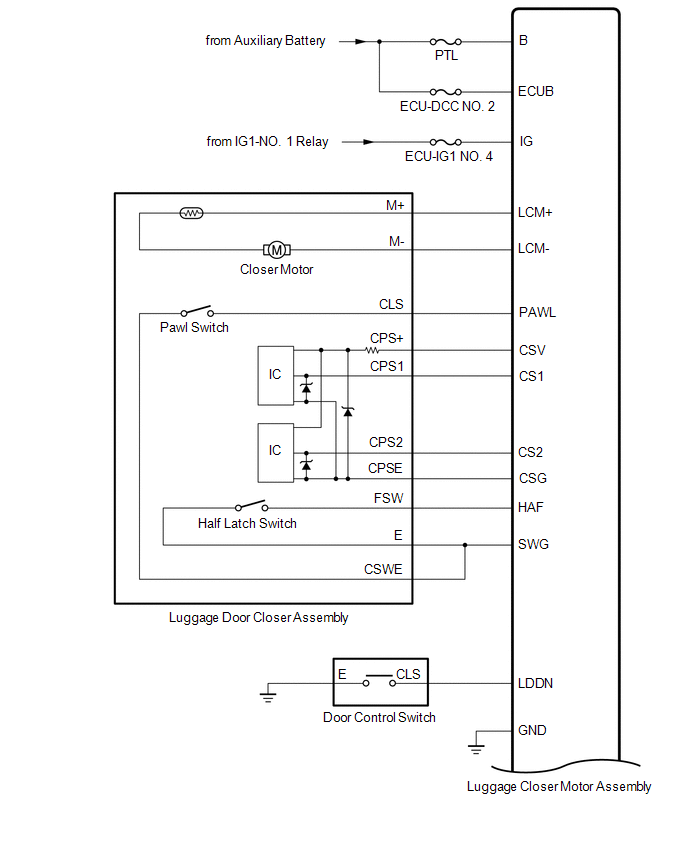
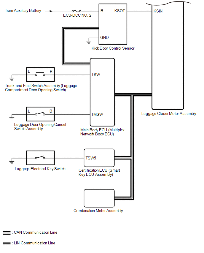
SYSTEM DIAGRAM
 Communication Table
 | Transmitting ECU | Receiving ECU | Signal | Communication Method |
|---|---|---|---|
| Certification ECU (smart key ECU assembly) | Main body ECU (multiplex network body ECU) | Luggage electrical key switch signal | CAN |
| Combination meter assembly | Main body ECU (multiplex network body ECU) | Vehicle speed signal | CAN |
| Main body ECU (multiplex network body ECU) | Luggage closer motor assembly |
| CAN |
| Main body ECU (multiplex network body ECU) | Kick door control sensor |
| LIN |
READ NEXT:
 How To Proceed With Troubleshooting
CAUTION / NOTICE / HINT HINT:
Use the following procedure to troubleshoot the power trunk lid system.
*: Use the Techstream.
PROCEDURE 1. VEHICLE BROUGHT TO WORKSHOP
NEXT
Check For Intermittent Problems
CHECK FOR INTERMITTENT PROBLEMS NOTICE:
If the vehicle or vehicle controls are operated (for example, during initial inspection when the vehicle is brought in for repair) before operation history h
Operation Check
OPERATION CHECK CHECK CUSTOMIZE PARAMETERS (a) The operation check below is based on the non-customized initial condition of the vehicle. Click here OPERATION CONDITIONS (a) Operation conditions wh
SEE MORE:
Pressure Control Solenoid "L" Circuit Short to Ground or Open (P08BA14)
DESCRIPTION Refer to DTC P08BA12. Click here DTC No. Detection Item DTC Detection Condition Trouble Area MIL Memory Note P08BA14 Pressure Control Solenoid "L" Circuit Short to Ground or Open While the vehicle is being driven so that gear changes occur, a short to ground or o
Sound Quality is Bad Only when Disc is Played (Volume is Too Low)
CAUTION / NOTICE / HINT NOTICE:
Depending on the parts that are replaced during vehicle inspection or maintenance, performing initialization, registration or calibration may be needed. Refer to Precaution for Navigation System.
Click here
When replacing the radio receiver assembly, always re
© 2016-2026 Copyright www.lexguide.net
