Lexus ES: Steering Vibrator System Missing Message (C1A7587)
DESCRIPTION
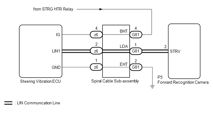
The forward recognition camera communicates with the steering vibration ECU via LIN communication.
If a communication error between the forward recognition camera and steering vibration ECU is detected, DTC C1A7587 is stored.
| DTC No. | Detection Item | DTC Detection Condition | Trouble Area |
|---|---|---|---|
| C1A7587 | Steering Vibrator System Missing Message | While the vehicle is being driven at 5 km/h (4 mph) or more and the lane control system is on, a LIN communication error is detected between the steering vibration ECU and forward recognition camera for approximately 5 minutes or more. |
|
WIRING DIAGRAM
CAUTION / NOTICE / HINT
NOTICE:
- When replacing the forward recognition camera, always replace it with a new one. If a forward recognition camera which was installed to another vehicle is used, the information stored in the forward recognition camera will not match the information from the vehicle. As a result, a DTC may be stored.
-
If the forward recognition camera has been replaced with a new one, be sure to perform forward recognition camera adjustment.
HINT:
Forward recognition camera adjustment can be performed by using either One Time Recognition or Sequential Recognition.
One Time Recognition: Click here
.gif)
Sequential Recognition: Click here
-
The vehicle is equipped with a Supplemental Restraint System (SRS) which includes components such as airbags. Before servicing (including removal or installation of parts), be sure to read the precaution for Supplemental Restraint System.
Click here
PROCEDURE
| 1. | INSPECT SPIRAL CABLE SUB-ASSEMBLY |
(a) Remove the spiral cable sub-assembly.
Click here
(b) Inspect the spiral cable sub-assembly.
Click here
| NG | .gif) | REPLACE SPIRAL CABLE SUB-ASSEMBLY |
|
.gif)
| 2. | INSPECT FORWARD RECOGNITION CAMERA (WAVEFORM) |
(a) Turn the engine switch off.
(b) Disconnect the G81 spiral cable sub-assembly connector.
(c) Turn the engine switch on (IG).
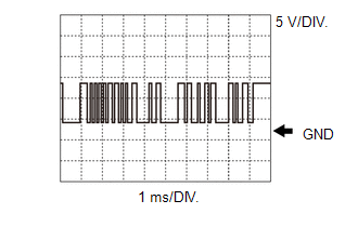
| (d) Using an oscilloscope, measure the waveform at G81 spiral cable sub-assembly connector. Measurement Condition:
NOTICE: The oscilloscope waveform is for reference only and does not include noise, fluctuations, etc. OK: A waveform similar to that in the illustration can be observed. |
|
(e) Connect the G81 spiral cable sub-assembly connector.
| NG | | GO TO STEP 5 |
|
| 3. | CHECK HARNESS AND CONNECTOR (SPIRAL CABLE SUB-ASSEMBLY - POWER SOURCE) |
(a) Disconnect the G81 spiral cable sub-assembly connector.
(b) Measure the voltage according to the value(s) in the table below.
Standard Voltage:
| Tester Connection | Condition | Specified Condition |
|---|---|---|
| G81-4 (BHT) - Body ground | Engine switch on (IG) | 11 to 14 V |
(c) Connect the G81 spiral cable sub-assembly connector.
| NG | | REPAIR OR REPLACE HARNESS OR CONNECTOR (SPIRAL CABLE SUB-ASSEMBLY - POWER SOURCE) |
|
| 4. | CHECK HARNESS AND CONNECTOR (SPIRAL CABLE SUB-ASSEMBLY - BODY GROUND) |
(a) Turn the engine switch off.
(b) Disconnect the G81 spiral cable sub-assembly connector.
(c) Measure the resistance according to the value(s) in the table below.
Standard Resistance:
| Tester Connection | Condition | Specified Condition |
|---|---|---|
| G81-2 (EHT) - Body ground | Always | Below 1 Ω |
(d) Connect the G81 spiral cable sub-assembly connector.
| OK | | REPLACE STEERING VIBRATION ECU |
| NG | | REPAIR OR REPLACE HARNESS OR CONNECTOR (SPIRAL CABLE SUB-ASSEMBLY - BODY GROUND) |
| 5. | CHECK HARNESS AND CONNECTOR (SPIRAL CABLE SUB-ASSEMBLY - FORWARD RECOGNITION CAMERA) |
(a) Turn the engine switch off.
(b) Disconnect the P5 forward recognition camera connector.
(c) Disconnect the G81 spiral cable sub-assembly connector.
(d) Measure the resistance according to the value(s) in the table below.
Standard Resistance:
| Tester Connection | Condition | Specified Condition |
|---|---|---|
| G81-1 (LDA) - P5-2 (STRV) | Always | Below 1 Ω |
| G81-1 (LDA) or P5-2 (STRV) - Body ground | Engine switch off | 10 kΩ or higher |
(e) Connect the G81 spiral cable sub-assembly connector.
(f) Connect the P5 forward recognition camera connector.
| OK | | REPLACE FORWARD RECOGNITION CAMERA |
| NG | | REPAIR OR REPLACE HARNESS OR CONNECTOR (SPIRAL CABLE SUB-ASSEMBLY - FORWARD RECOGNITION CAMERA) |
READ NEXT:
 Front Recognition Camera Optical Axis Misalignment Malfunction (C1AA800)
DESCRIPTION The forward recognition camera monitors its optical axis status. If it determines that the optical axis alignment has become misaligned, it will store DTC C1AA800. DTC No. Detection I
Front Recognition Camera Heater Malfunction (C1AAE00)
DESCRIPTION The forward recognition camera controls the flow of current to the forward recognition with heater hood sub-assembly. If the forward recognition camera detects a malfunction in the forward
Lost Communication with ECM/PCM "A" Missing Message (U010087,U012587,U012687,U012987,U014087)
DESCRIPTION When a malfunction is detected between various ECUs and sensors, these DTCs are stored. DTC No. Detection Item DTC Detection Condition Trouble Area U010087 Lost Communicatio
SEE MORE:
Accumulator Pressure Sensor Stuck (C14D5)
DESCRIPTION The accumulator pressure sensor is built into the brake booster with master cylinder assembly and detects the accumulator pressure. If the skid control ECU (brake booster with master cylinder assembly) detects that the accumulator pressure sensor value is below the threshold, operation o
Vehicle Speed Sensor "A" No Signal (P050031)
DESCRIPTION The speed sensor detects the wheel speed and sends the appropriate signals to the skid control ECU. The skid control ECU converts these wheel speed signals into a pulse signal and outputs it to the ECM via the combination meter. The ECM determines the vehicle speed based on the frequency
