Lexus ES: Sound Signal Circuit between Radio Receiver and Stereo Jack Adapter
DESCRIPTION
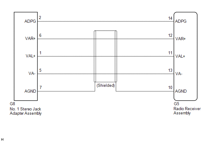
The No. 1 stereo jack adapter assembly sends the sound signal from an external device to the radio receiver assembly via this circuit.
WIRING DIAGRAM
PROCEDURE
| 1. | CHECK HARNESS AND CONNECTOR (RADIO RECEIVER ASSEMBLY - NO. 1 STEREO JACK ADAPTER ASSEMBLY) |
(a) Disconnect the G5 radio receiver assembly connector.
(b) Disconnect the G8 No. 1 stereo jack adapter assembly connector.
(c) Measure the resistance according to the value(s) in the table below.
Standard Resistance:
| Tester Connection | Condition | Specified Condition |
|---|---|---|
| G5-14 (ADPG) - G8-2 (ADPG) | Always | Below 1 Ω |
| G5-10 (AGND) - G8-7 (AGND) | Always | Below 1 Ω |
| G5-12 (VAR+) - G8-6 (VAR+) | Always | Below 1 Ω |
| G5-11 (VAL+) - G8-1 (VAL+) | Always | Below 1 Ω |
| G5-13 (VA-) - G8-5 (VA-) | Always | Below 1 Ω |
| G5-14 (ADPG) or G8-2 (ADPG) - Body ground | Always | 10 kΩ or higher |
| G5-10 (AGND) or G8-7 (AGND) - Body ground | Always | 10 kΩ or higher |
| G5-12 (VAR+) or G8-6 (VAR+) - Body ground | Always | 10 kΩ or higher |
| G5-11 (VAL+) or G8-1 (VAL+) - Body ground | Always | 10 kΩ or higher |
| G5-13 (VA-) or G8-5 (VA-) - Body ground | Always | 10 kΩ or higher |
| OK |  | PROCEED TO NEXT SUSPECTED AREA SHOWN IN PROBLEM SYMPTOMS TABLE |
.gif)
| NG | | REPAIR OR REPLACE HARNESS OR CONNECTOR |
READ NEXT:
 Speaker Circuit
DESCRIPTION If there is a short in a speaker circuit, the stereo component amplifier assembly detects it and stops output to the speakers. Thus sound cannot be heard from the speakers even if there is
Start Up Signal Circuit between Radio Receiver Assembly and Navigation ECU
DESCRIPTION This circuit includes the navigation ECU and radio receiver assembly. WIRING DIAGRAM PROCEDURE 1. CHECK HARNESS AND CONNECTOR (RADIO RECEIVER ASSEMBLY - NAVIGATION ECU) (a) Disco
Steering Pad Switch Circuit
DESCRIPTION This circuit sends an operation signal from the steering pad switch assembly to the radio receiver assembly. If there is an open in the circuit, the navigation system cannot be operated us
SEE MORE:
Terminals Of Ecu
TERMINALS OF ECU CHECK WINDSHIELD WIPER MOTOR ASSEMBLY (a) Disconnect the A38 windshield wiper motor assembly connector. (b) Measure the voltage and resistance on the wire harness side connector according to the value(s) in the table below. Terminal No. (Symbol) Wiring Color Terminal Descrip
Camshaft Position Sensor "B" Bank 1 Circuit Short to Ground (P036511,P036515)
DESCRIPTION The camshaft position sensor (for exhaust camshaft) (EV1 signal) consists of a magnet and MRE (Magneto Resistance Element). The exhaust camshaft has a timing rotor for the camshaft position sensor. When the exhaust camshaft rotates, changes occur in the air gaps between the timing rotor
