Lexus ES: Right Rear Wheel Speed Sensor Internal Electronic Failure (C051249)
DESCRIPTION
When the system is starting up and the skid control ECU (brake actuator assembly) detects a speed sensor circuit malfunction via the speed sensor circuit self-diagnosis function, this DTC is stored.
| DTC No. | Detection Item | DTC Detection Condition | Trouble Area |
|---|---|---|---|
| C051249 | Right Rear Wheel Speed Sensor Internal Electronic Failure | A circuit malfunction in the speed sensor is detected during the self test. |
|
WIRING DIAGRAM
Refer to DTC C051212.
Click here .gif)
CAUTION / NOTICE / HINT
NOTICE:
-
After replacing the skid control ECU (brake actuator assembly), perform acceleration sensor zero point calibration and store system information memorization.
Click here
-
After replacing or removing and installing a speed sensor, perform Dealer Mode (Signal Check) inspection to confirm that the speed sensors are operating correctly.
Click here
PROCEDURE
| 1. | CHECK HARNESS AND CONNECTOR (SENSOR CIRCUIT) |
| (a) Make sure that there is no looseness at the locking part and the connecting part of the connectors. OK: The connector is securely connected. |
|
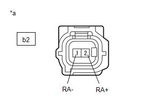
(b) Disconnect the b2 rear speed sensor RH (rear axle hub and bearing assembly RH) connector.
(c) Check both the connector case and the terminals for deformation and corrosion.
OK:
No deformation or corrosion.
(d) Turn the engine switch on (IG).
(e) Measure the voltage according to the value(s) in the table below.
Standard Voltage:
| Tester Connection | Condition | Specified Condition |
|---|---|---|
| b2-2 (RA+) - b2-1 (RA-) | Engine switch on (IG) | 11 to 14 V |
| Result | Proceed to |
|---|---|
| OK | A |
| NG (w/o AVS) | B |
| NG (w/ AVS) | C |
| B |  | GO TO STEP 11 |
| C | | GO TO STEP 16 |
|

| 2. | CHECK HARNESS AND CONNECTOR (SENSOR POWER SOURCE CIRCUIT) |
| (a) Make sure that there is no looseness at the locking part and the connecting part of the connectors. OK: The connector is securely connected. |
|
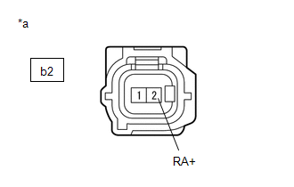
(b) Disconnect the b2 rear speed sensor RH (rear axle hub and bearing assembly RH) connector.
(c) Check both the connector case and the terminals for deformation and corrosion.
OK:
No deformation or corrosion.
(d) Measure the voltage according to the value(s) in the table below.
Standard Voltage:
| Tester Connection | Condition | Specified Condition |
|---|---|---|
| b2-2 (RA+) - Body ground | Engine switch off | Below 1.5 V |
| Result | Proceed to |
|---|---|
| OK (w/o AVS) | A |
| OK (w/ AVS) | B |
| NG (w/o AVS) | C |
| NG (w/ AVS) | D |
| B | | GO TO STEP 5 |
| C | | GO TO STEP 7 |
| D | | GO TO STEP 9 |
|
| 3. | INSPECT NO. 1 PARKING BRAKE WIRE ASSEMBLY |
| (a) Make sure that there is no looseness at the locking part and the connecting part of the connectors. OK: The connector is securely connected. |
|
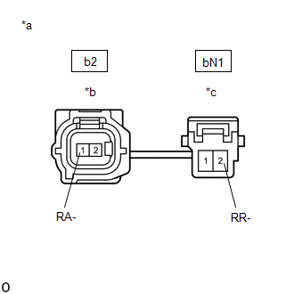
(b) Disconnect the b2 skid control sensor wire RH (No. 1 parking brake wire assembly) connector.
(c) Disconnect the bN1 skid control sensor wire RH (No. 1 parking brake wire assembly) connector.
(d) Check both the connector case and the terminals for deformation and corrosion.
OK:
No deformation or corrosion.
(e) Measure the resistance according to the value(s) in the table below.
Standard Resistance:
| Tester Connection | Condition | Specified Condition |
|---|---|---|
| b2-1 (RA-) or bN1-2 (RR-) - Body ground and other terminals | Always | 10 kΩ or higher |
| NG | | REPLACE NO. 1 PARKING BRAKE WIRE ASSEMBLY |
|
| 4. | CHECK HARNESS AND CONNECTOR (NO. 1 PARKING BRAKE WIRE ASSEMBLY - BRAKE ACTUATOR ASSEMBLY) |
(a) Make sure that there is no looseness at the locking part and the connecting part of the connectors.
OK:
The connector is securely connected.
(b) Disconnect the A40 skid control ECU (brake actuator assembly) connector.
(c) Disconnect the bN1 skid control sensor wire RH (No. 1 parking brake wire assembly) connector.
(d) Check both the connector case and the terminals for deformation and corrosion.
OK:
No deformation or corrosion.
(e) Measure the resistance according to the value(s) in the table below.
Standard Resistance:
| Tester Connection | Condition | Specified Condition |
|---|---|---|
| bN1-2 (RR-) or A40-37 (RR-) - Body ground | Always | 10 kΩ or higher |
| OK | | REPLACE REAR AXLE HUB AND BEARING ASSEMBLY RH |
| NG | | REPAIR OR REPLACE HARNESS OR CONNECTOR |
| 5. | INSPECT NO. 1 PARKING BRAKE WIRE ASSEMBLY |
| (a) Make sure that there is no looseness at the locking part and the connecting part of the connectors. OK: The connector is securely connected. |
|
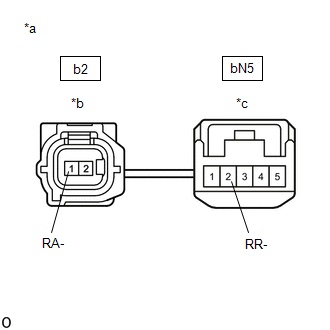
(b) Disconnect the b2 skid control sensor wire RH (No. 1 parking brake wire assembly) connector.
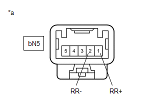
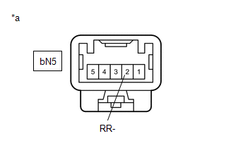
(c) Disconnect the bN5 skid control sensor wire RH (No. 1 parking brake wire assembly) connector.
(d) Check both the connector case and the terminals for deformation and corrosion.
OK:
No deformation or corrosion.
(e) Measure the resistance according to the value(s) in the table below.
Standard Resistance:
| Tester Connection | Condition | Specified Condition |
|---|---|---|
| b2-1 (RA-) or bN5-2 (RR-) - Body ground and other terminals | Always | 10 kΩ or higher |
| NG | | REPLACE NO. 1 PARKING BRAKE WIRE ASSEMBLY |
|
| 6. | CHECK HARNESS AND CONNECTOR (NO. 1 PARKING BRAKE WIRE ASSEMBLY - BRAKE ACTUATOR ASSEMBLY) |
(a) Make sure that there is no looseness at the locking part and the connecting part of the connectors.
OK:
The connector is securely connected.
(b) Disconnect the A40 skid control ECU (brake actuator assembly) connector.
(c) Disconnect the bN5 skid control sensor wire RH (No. 1 parking brake wire assembly) connector.
(d) Check both the connector case and the terminals for deformation and corrosion.
OK:
No deformation or corrosion.
(e) Measure the resistance according to the value(s) in the table below.
Standard Resistance:
| Tester Connection | Condition | Specified Condition |
|---|---|---|
| bN5-2 (RR-) or A40-37 (RR-) - Body ground | Always | 10 kΩ or higher |
| OK | | REPLACE REAR AXLE HUB AND BEARING ASSEMBLY RH |
| NG | | REPAIR OR REPLACE HARNESS OR CONNECTOR |
| 7. | CHECK HARNESS AND CONNECTOR (SENSOR POWER SOURCE CIRCUIT) |
| (a) Make sure that there is no looseness at the locking part and the connecting part of the connectors. OK: The connector is securely connected. |
|
(b) Disconnect the bN1 skid control sensor wire RH (No. 1 parking brake wire assembly) connector.
(c) Check both the connector case and the terminals for deformation and corrosion.
OK:
No deformation or corrosion.
(d) Measure the voltage according to the value(s) in the table below.
Standard Voltage:
| Tester Connection | Condition | Specified Condition |
|---|---|---|
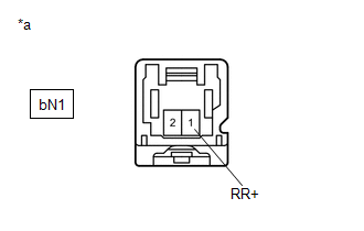
| bN1-1 (RR+) - Body ground | Engine switch off | Below 1.5 V |
| OK | | REPLACE NO. 1 PARKING BRAKE WIRE ASSEMBLY |
|
| 8. | CHECK HARNESS AND CONNECTOR (NO. 1 PARKING BRAKE WIRE ASSEMBLY - BRAKE ACTUATOR ASSEMBLY) |
| (a) Make sure that there is no looseness at the locking part and the connecting part of the connectors. OK: The connector is securely connected. |
|
(b) Disconnect the A40 skid control ECU (brake actuator assembly) connector.
(c) Disconnect the bN1 skid control sensor wire RH (No.1 parking brake wire assembly) connector.
(d) Check both the connector case and the terminals for deformation and corrosion.
OK:
No deformation or corrosion.
(e) Measure the voltage according to the value(s) in the table below.
Standard Voltage:
| Tester Connection | Condition | Specified Condition |
|---|---|---|
| bN1-1 (RR+) - Body ground | Always | Below 1.5 V |
| OK | | REPLACE BRAKE ACTUATOR ASSEMBLY |
| NG | | REPAIR OR REPLACE HARNESS OR CONNECTOR |
| 9. | CHECK HARNESS AND CONNECTOR (SENSOR POWER SOURCE CIRCUIT) |
| (a) Make sure that there is no looseness at the locking part and the connecting part of the connectors. OK: The connector is securely connected. |
|
(b) Disconnect the bN5 skid control sensor wire RH (No. 1 parking brake wire assembly) connector.
(c) Check both the connector case and the terminals for deformation and corrosion.
OK:
No deformation or corrosion.
(d) Measure the voltage according to the value(s) in the table below.
Standard Voltage:
| Tester Connection | Condition | Specified Condition |
|---|---|---|
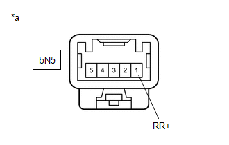
| bN5-1 (RR+) - Body ground | Engine switch off | Below 1.5 V |
| OK | | REPLACE NO. 1 PARKING BRAKE WIRE ASSEMBLY |
|
| 10. | CHECK HARNESS AND CONNECTOR (NO. 1 PARKING BRAKE WIRE ASSEMBLY - BRAKE ACTUATOR ASSEMBLY) |
| (a) Make sure that there is no looseness at the locking part and the connecting part of the connectors. OK: The connector is securely connected. |
|
(b) Disconnect the A40 skid control ECU (brake actuator assembly) connector.
(c) Disconnect the bN5 skid control sensor wire RH (No. 1 parking brake wire assembly) connector.
(d) Check both the connector case and the terminals for deformation and corrosion.
OK:
No deformation or corrosion.
(e) Measure the voltage according to the value(s) in the table below.
Standard Voltage:
| Tester Connection | Condition | Specified Condition |
|---|---|---|
| bN5-1 (RR+) - Body ground | Always | Below 1.5 V |
| OK | | REPLACE BRAKE ACTUATOR ASSEMBLY |
| NG | | REPAIR OR REPLACE HARNESS OR CONNECTOR |
| 11. | CHECK HARNESS AND CONNECTOR (SENSOR CIRCUIT) |
| (a) Make sure that there is no looseness at the locking part and the connecting part of the connectors. OK: The connector is securely connected. |
|
(b) Disconnect the bN1 skid control sensor wire RH (No. 1 parking brake wire assembly) connector.
(c) Check both the connector case and the terminals for deformation and corrosion.
OK:
No deformation or corrosion.
(d) Turn the engine switch on (IG).
(e) Measure the voltage according to the value(s) in the table below.
Standard Voltage:
| Tester Connection | Condition | Specified Condition |
|---|---|---|
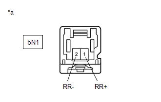
| bN1-1 (RR+) - bN1-2 (RR-) | Engine switch on (IG) | 11 to 14 V |
| OK | | REPLACE NO. 1 PARKING BRAKE WIRE ASSEMBLY |
|
| 12. | CHECK HARNESS AND CONNECTOR (SENSOR POWER SOURCE CIRCUIT) |
| (a) Make sure that there is no looseness at the locking part and the connecting part of the connectors. OK: The connector is securely connected. |
|
(b) Disconnect the bN1 skid control sensor wire RH (No. 1 parking brake wire assembly) connector.
(c) Check both the connector case and the terminals for deformation and corrosion.
OK:
No deformation or corrosion.
(d) Turn the engine switch on (IG).
(e) Measure the voltage according to the value(s) in the table below.
Standard Voltage:
| Tester Connection | Condition | Specified Condition |
|---|---|---|
| bN1-1 (RR+) - Body ground | Engine switch on (IG) | 11 to 14 V |
| NG | | GO TO STEP 15 |
|
| 13. | CHECK HARNESS AND CONNECTOR (NO. 1 PARKING BRAKE WIRE ASSEMBLY - BRAKE ACTUATOR ASSEMBLY) |
| (a) Make sure that there is no looseness at the locking part and the connecting part of the connectors. OK: The connector is securely connected. |
|
(b) Disconnect the A40 skid control ECU (brake actuator assembly) connector.
(c) Disconnect the bN1 skid control sensor wire RH (No. 1 parking brake wire assembly) connector.
(d) Check both the connector case and the terminals for deformation and corrosion.
OK:
No deformation or corrosion.
(e) Measure the voltage according to the value(s) in the table below.
Standard Voltage:
| Tester Connection | Condition | Specified Condition |
|---|---|---|
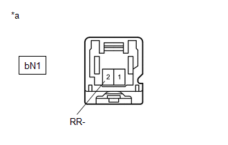
| bN1-2 (RR-) - Body ground | Always | Below 1.5 V |
| NG | | REPAIR OR REPLACE HARNESS OR CONNECTOR |
|
| 14. | CHECK HARNESS AND CONNECTOR (NO. 1 PARKING BRAKE WIRE ASSEMBLY - BRAKE ACTUATOR ASSEMBLY) |
(a) Make sure that there is no looseness at the locking part and the connecting part of the connectors.
OK:
The connector is securely connected.
(b) Disconnect the A40 skid control ECU (brake actuator assembly) connector.
(c) Disconnect the bN1 skid control sensor wire RH (No. 1 parking brake wire assembly) connector.
(d) Check both the connector case and the terminals for deformation and corrosion.
OK:
No deformation or corrosion.
(e) Measure the resistance according to the value(s) in the table below.
Standard Resistance:
| Tester Connection | Condition | Specified Condition |
|---|---|---|
| bN1-2 (RR-) - A40-37 (RR-) | Always | Below 1 Ω |
| bN1-1 (RR+) or A40-22 (RR+) - bN1-2 (RR-) or A40-37 (RR-) | Always | 10 kΩ or higher |
| OK | | REPLACE BRAKE ACTUATOR ASSEMBLY |
| NG | | REPAIR OR REPLACE HARNESS OR CONNECTOR |
| 15. | CHECK HARNESS AND CONNECTOR (NO. 1 PARKING BRAKE WIRE ASSEMBLY - BRAKE ACTUATOR ASSEMBLY) |
(a) Make sure that there is no looseness at the locking part and the connecting part of the connectors.
OK:
The connector is securely connected.
(b) Disconnect the A40 skid control ECU (brake actuator assembly) connector.
(c) Disconnect the bN1 skid control sensor wire RH (No. 1 parking brake wire assembly) connector.
(d) Check both the connector case and the terminals for deformation and corrosion.
OK:
No deformation or corrosion.
(e) Measure the resistance according to the value(s) in the table below.
Standard Resistance:
| Tester Connection | Condition | Specified Condition |
|---|---|---|
| bN1-1 (RR+) - A40-22 (RR+) | Always | Below 1 Ω |
| bN1-1 (RR+) or A40-22 (RR+) - Body ground | Always | 10 kΩ or higher |
| OK | | REPLACE BRAKE ACTUATOR ASSEMBLY |
| NG | | REPAIR OR REPLACE HARNESS OR CONNECTOR |
| 16. | CHECK HARNESS AND CONNECTOR (SENSOR CIRCUIT) |
| (a) Make sure that there is no looseness at the locking part and the connecting part of the connectors. OK: The connector is securely connected. |
|
(b) Disconnect the bN5 skid control sensor wire RH (No. 1 parking brake wire assembly) connector.
(c) Check both the connector case and the terminals for deformation and corrosion.
OK:
No deformation or corrosion.
(d) Turn the engine switch on (IG).
(e) Measure the voltage according to the value(s) in the table below.
Standard Voltage:
| Tester Connection | Condition | Specified Condition |
|---|---|---|
| bN5-1 (RR+) - bN5-2 (RR-) | Engine switch on (IG) | 11 to 14 V |
| OK | | REPLACE NO. 1 PARKING BRAKE WIRE ASSEMBLY |
|
| 17. | CHECK HARNESS AND CONNECTOR (SENSOR POWER SOURCE CIRCUIT) |
| (a) Make sure that there is no looseness at the locking part and the connecting part of the connectors. OK: The connector is securely connected. |
|
(b) Disconnect the bN5 skid control sensor wire RH (No. 1 parking brake wire assembly) connector.
(c) Check both the connector case and the terminals for deformation and corrosion.
OK:
No deformation or corrosion.
(d) Turn the engine switch on (IG).
(e) Measure the voltage according to the value(s) in the table below.
Standard Voltage:
| Tester Connection | Condition | Specified Condition |
|---|---|---|
| bN5-1 (RR+) - Body ground | Engine switch on (IG) | 11 to 14 V |
| NG | | GO TO STEP 20 |
|
| 18. | CHECK HARNESS AND CONNECTOR (NO. 1 PARKING BRAKE WIRE ASSEMBLY - BRAKE ACTUATOR ASSEMBLY) |
| (a) Make sure that there is no looseness at the locking part and the connecting part of the connectors. OK: The connector is securely connected. |
|
(b) Disconnect the A40 skid control ECU (brake actuator assembly) connector.
(c) Disconnect the bN5 skid control sensor wire RH (No. 1 parking brake wire assembly) connector.
(d) Check both the connector case and the terminals for deformation and corrosion.
OK:
No deformation or corrosion.
(e) Measure the voltage according to the value(s) in the table below.
Standard Voltage:
| Tester Connection | Condition | Specified Condition |
|---|---|---|
| bN5-2 (RR-) - Body ground | Always | Below 1.5 V |
| NG | | REPAIR OR REPLACE HARNESS OR CONNECTOR |
|
| 19. | CHECK HARNESS AND CONNECTOR (NO. 1 PARKING BRAKE WIRE ASSEMBLY - BRAKE ACTUATOR ASSEMBLY) |
(a) Make sure that there is no looseness at the locking part and the connecting part of the connectors.
OK:
The connector is securely connected.
(b) Disconnect the A40 skid control ECU (brake actuator assembly) connector.
(c) Disconnect the bN5 skid control sensor wire RH (No. 1 parking brake wire assembly) connector.
(d) Check both the connector case and the terminals for deformation and corrosion.
OK:
No deformation or corrosion.
(e) Measure the resistance according to the value(s) in the table below.
Standard Resistance:
| Tester Connection | Condition | Specified Condition |
|---|---|---|
| bN5-2 (RR-) - A40-37 (RR-) | Always | Below 1 Ω |
| bN5-1 (RR+) or A40-22 (RR+) - bN5-2 (RR-) or A40-37 (RR-) | Always | 10 kΩ or higher |
| OK | | REPLACE BRAKE ACTUATOR ASSEMBLY |
| NG | | REPAIR OR REPLACE HARNESS OR CONNECTOR |
| 20. | CHECK HARNESS AND CONNECTOR (NO. 1 PARKING BRAKE WIRE ASSEMBLY - BRAKE ACTUATOR ASSEMBLY) |
(a) Make sure that there is no looseness at the locking part and the connecting part of the connectors.
OK:
The connector is securely connected.
(b) Disconnect the A40 skid control ECU (brake actuator assembly) connector.
(c) Disconnect the bN5 skid control sensor wire RH (No. 1 parking brake wire assembly) connector.
(d) Check both the connector case and the terminals for deformation and corrosion.
OK:
No deformation or corrosion.
(e) Measure the resistance according to the value(s) in the table below.
Standard Resistance:
| Tester Connection | Condition | Specified Condition |
|---|---|---|
| bN5-1 (RR+) - A40-22 (RR+) | Always | Below 1 Ω |
| bN5-1 (RR+) or A40-22 (RR+) - Body ground | Always | 10 kΩ or higher |
| OK | | REPLACE BRAKE ACTUATOR ASSEMBLY |
| NG | | REPAIR OR REPLACE HARNESS OR CONNECTOR |
READ NEXT:
 Right Rear Wheel Speed Sensor Internal Electronic Failure (C051249)
DESCRIPTION When the system is starting up and the skid control ECU (brake actuator assembly) detects a speed sensor circuit malfunction via the speed sensor circuit self-diagnosis function, this DTC
Multi-axis Acceleration Sensor Module "A" Component Internal Failure (C052096)
DESCRIPTION The airbag ECU assembly has a built-in yaw rate and acceleration sensor and detects the vehicle condition. The skid control ECU (brake actuator assembly) receives signals from the yaw rate
Steering Angle Sensor Module Calibration / Parameter Memory Failure (C052646)
DESCRIPTION When the vehicle is being driven in a straight line at 15 km/h (9 mph) for 1 second or more, the skid control ECU (brake actuator assembly) calculates the steering angle sensor zero point
SEE MORE:
Installation
INSTALLATION PROCEDURE 1. INSTALL TRANSFER ASSEMBLY (a) Using SST and a 17 mm union nut wrench, install the transfer assembly to the automatic transaxle assembly with the 8 nuts. SST: 09961-00950 Torque: Specified tightening torque : 68.6 N·m {700 kgf·cm, 51 ft·lbf} HINT:
Calculate the to
Disposal
DISPOSAL PROCEDURE 1. DISPOSE OF HOOD SUPPORT ASSEMBLY (a) Secure the hood support assembly horizontally in a vise with the piston rod pulled out. (b) Wearing safety glasses, gradually cut a part within the area (a) shown in the illustration using a metal saw to release the gas. Specification:
