Lexus ES: Removal
REMOVAL
CAUTION / NOTICE / HINT
The necessary procedures (adjustment, calibration, initialization, or registration) that must be performed after parts are removed and installed, or replaced during black out tape removal/installation are shown below.
Necessary Procedure After Parts Removed/Installed/Replaced (for HV Model)| Replaced Part or Performed Procedure | Necessary Procedure | Effect/Inoperative Function When Necessary Procedures are not Performed | Link |
|---|---|---|---|
|
*: When performing learning using the Techstream.
Click here | |||
| Disconnect cable from negative auxiliary battery terminal | Perform steering sensor zero point calibration | Lane Control System | |
| Pre-collision System | |||
| Parking Support Brake System* | |||
| Lighting System | |||
| Memorize steering angle neutral point | Parking Assist Monitor System | | |
| Panoramic View Monitor System | | ||
| Initialize power trunk lid system | Power Trunk Lid System | | |
| Initialize power window control system |
| |
NOTICE:
- After the power switch is turned off, the radio receiver assembly records various types of memory and settings. As a result, after turning the power switch off, make sure to wait at least 85 seconds before disconnecting the cable from the negative (-) auxiliary battery terminal. (for Audio and Visual System)
- After the power switch is turned off, the radio receiver assembly records various types of memory and settings. As a result, after turning the power switch off, make sure to wait at least 85 seconds before disconnecting the cable from the negative (-) auxiliary battery terminal. (for Navigation System)
| Replaced Part or Performed Procedure | Necessary Procedure | Effect/Inoperative Function When Necessary Procedures are not Performed | Link |
|---|---|---|---|
|
*: When performing learning using the Techstream.
Click here | |||
| Disconnect cable from negative battery terminal | Perform steering sensor zero point calibration | Lane Control System | |
| Pre-collision System | |||
| Parking Support Brake System* | |||
| Lighting System | |||
| Memorize steering angle neutral point | Parking Assist Monitor System | | |
| Panoramic View Monitor System | | ||
| Initialize power trunk lid system | Power Trunk Lid System | | |
| Initialize power window control system |
| |
NOTICE:
- After the engine switch is turned off, the radio receiver assembly records various types of memory and settings. As a result, after turning the engine switch off, make sure to wait at least 85 seconds before disconnecting the cable from the negative (-) battery terminal. (for Audio and Visual System)
- After the engine switch is turned off, the radio receiver assembly records various types of memory and settings. As a result, after turning the engine switch off, make sure to wait at least 85 seconds before disconnecting the cable from the negative (-) battery terminal. (for Navigation System)
HINT:
- Use the same procedure for the RH side and LH side.
- The following procedure is for the LH side.
PROCEDURE
1. PRECAUTION
NOTICE:
After turning the engine switch (for Gasoline Model) or power switch (for HV Model) off, waiting time may be required before disconnecting the cable from the negative (-) auxiliary battery terminal. Therefore, make sure to read the disconnecting the cable from the negative (-) auxiliary battery terminal notices before proceeding with work.
2. DISCONNECT CABLE FROM NEGATIVE AUXILIARY BATTERY TERMINAL
for 2GR-FKS:
Click here .gif)
for A25A-FXS:
Click here
3. REMOVE REAR POWER WINDOW REGULATOR SWITCH ASSEMBLY WITH REAR DOOR UPPER ARMREST BASE PANEL
Click here
4. REMOVE REAR DOOR TRIM UPPER PAD
Click here
5. REMOVE COURTESY LIGHT ASSEMBLY
Click here
6. REMOVE REAR DOOR TRIM BOARD SUB-ASSEMBLY
Click here
7. REMOVE REAR SIDE CURTAIN ASSEMBLY (w/ Rear Door Sunshade)
Click here
8. REMOVE CURTAIN HOOK (w/ Rear Door Sunshade)
Click here
9. REMOVE REAR DOOR SERVICE HOLE COVER
Click here
10. REMOVE REAR DOOR NO. 2 SERVICE HOLE COVER
Click here
11. REMOVE REAR DOOR NO. 2 VENT SEAL
Click here
12. REMOVE REAR DOOR PANEL PROTECTOR
Click here
13. REMOVE REAR DOOR GLASS RUN
Click here
14. DISCONNECT REAR DOOR WEATHERSTRIP
Click here
15. REMOVE REAR DOOR WINDOW DIVISION BAR SUB-ASSEMBLY
Click here
16. REMOVE REAR DOOR QUARTER WINDOW GLASS SUB-ASSEMBLY
Click here
17. REMOVE REAR DOOR GLASS SUB-ASSEMBLY
Click here
18. REMOVE REAR DOOR FRAME GARNISH
Click here
19. REMOVE REAR DOOR CHECK ASSEMBLY
Click here
20. REMOVE REAR DOOR WEATHERSTRIP
Click here
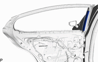
21. REMOVE FRONT INNER BLACK OUT TAPE
HINT:
When removing the front inner black out tape, heat the vehicle body and front inner black out tape using a heat light.
Heating Temperature| Item | Temperature |
|---|---|
| Front Inner Black Out Tape and Vehicle Body | 40 to 60°C (104 to 140°F) |
CAUTION:
- Do not touch the heat light and heated parts, touching the heat light may result in burns.
- Touching heated parts for a long time may result in burns.
.png)
| *a | Heated Part |
| *b | Heat Light |
NOTICE:
Do not heat the vehicle body excessively.
(a) Using a heat light, heat the front inner black out tape and vehicle body.
| (b) Pull back on one of the ends of the front inner black out tape to remove it. HINT: When pulling on the front inner black out tape, pull it parallel to the vehicle body. |
|
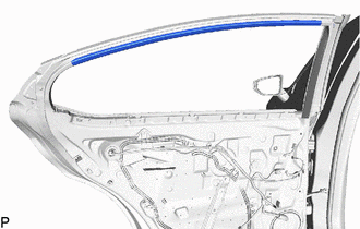
22. REMOVE UPPER INNER BLACK OUT TAPE
HINT:
When removing the upper inner black out tape, heat the vehicle body and upper inner black out tape using a heat light.
Heating Temperature| Item | Temperature |
|---|---|
| Upper Inner Black Out Tape and Vehicle Body | 40 to 60°C (104 to 140°F) |
CAUTION:
- Do not touch the heat light and heated parts, touching the heat light may result in burns.
- Touching heated parts for a long time may result in burns.
| *a | Heated Part |
| *b | Heat Light |
NOTICE:
Do not heat the vehicle body excessively.
(a) Using a heat light, heat the upper inner black out tape and vehicle body.
| (b) Pull back on one of the ends of the upper inner black out tape to remove it. HINT: When pulling on the upper inner black out tape, pull it parallel to the vehicle body. |
|
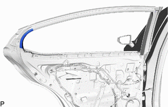
23. REMOVE REAR INNER BLACK OUT TAPE
HINT:
When removing the rear inner black out tape, heat the vehicle body and rear inner black out tape using a heat light.
Heating Temperature| Item | Temperature |
|---|---|
| Rear inner black out tape and Vehicle Body | 40 to 60°C (104 to 140°F) |
CAUTION:
- Do not touch the heat light and heated parts, touching the heat light may result in burns.
- Touching heated parts for a long time may result in burns.
| *a | Heated Part |
| *b | Heat Light |
NOTICE:
Do not heat the vehicle body excessively.
(a) Using a heat light, heat the rear inner black out tape and vehicle body.
| (b) Pull back on one of the ends of the rear inner black out tape to remove it. HINT: When pulling on the rear inner black out tape, pull it parallel to the vehicle body. |
|
READ NEXT:
 Installation
INSTALLATION CAUTION / NOTICE / HINT HINT:
Use the same procedure for the RH side and LH side.
The following procedure is for the LH side.
PROCEDURE 1. PRECAUTION NOTICE: After turning the eng
Components
COMPONENTS ILLUSTRATION *1 COOL AIR INTAKE DUCT SEAL *2 FRONT BUMPER ASSEMBLY *3 FRONT BUMPER SIDE MOUNTING BRACKET - - ILLUSTRATION *A for Bar Type Radiator Grille -
SEE MORE:
Cruise Main Indicator Light Circuit
DESCRIPTION When the dynamic radar cruise control system is turned on using the cruise control main switch, the cruise control indicator (vehicle-to-vehicle distance control mode) illuminates. The hybrid vehicle control ECU uses this and other indicators to indicate the status (presence or absence o
Remote Control System does not Operate
DESCRIPTION The main body ECU (multiplex network body ECU) receives remote control signals from the driver door key cylinder or electrical key transmitter sub-assembly. Then, the main body ECU (multiplex network body ECU) activates the power window motor and sends the remote control signals to the s
