
Lexus ES: Removal
REMOVAL
CAUTION / NOTICE / HINT
The necessary procedures (adjustment, calibration, initialization, or registration) that must be performed after parts are removed and installed, or replaced during mass air flow meter sub-assembly removal/installation are shown below.
Necessary Procedures After Parts Removed/Installed/Replaced| Replaced Part or Performed Procedure | Necessary Procedure | Effect/Inoperative Function when Necessary Procedure not Performed | Link |
|---|---|---|---|
| Replacement of mass air flow meter sub-assembly | Inspection after repair |
| |
.gif)
PROCEDURE
1. REMOVE MASS AIR FLOW METER SUB-ASSEMBLY
| (a) Disconnect the mass air flow meter sub-assembly connector. |
|
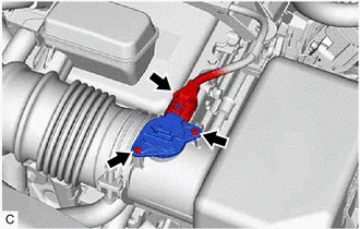
(b) Remove the 2 screws and mass air flow meter sub-assembly from the air cleaner cap sub-assembly.
NOTICE:
If the mass air flow meter sub-assembly has been struck or dropped, replace it.
READ NEXT:
 Inspection
INSPECTION PROCEDURE 1. INSPECT MASS AIR FLOW METER SUB-ASSEMBLY (a) Perform a visual check for any foreign matter on the intake air temperature sensor (thermistor) of the mass air flow meter sub-a
Installation
INSTALLATION PROCEDURE 1. INSTALL MASS AIR FLOW METER SUB-ASSEMBLY HINT: Perform "Inspection After Repair" after replacing the mass air flow meter sub-assembly. Click here (a) Install the mass ai
Relay
On-vehicle InspectionON-VEHICLE INSPECTION PROCEDURE 1. INSPECT MAIN RELAY (EFI-MAIN NO. 1) (a) Measure the resistance according to the value(s) in the table below. Standard Resistance: Tester
SEE MORE:
PBD/PTL Closer Operation (B2250)
DESCRIPTION DTC B2250 is stored when there is a malfunction in the closer pulse sensor circuit of the luggage door closer assembly and when a normal waveform is not input for the closer pulse during power trunk lid operation. DTC No. Detection Item DTC Detection Condition Trouble Area B
Hybrid/EV Battery Energy Control Module EEPROM Data Memory Failure (P062F44)
DESCRIPTION The battery ECU assembly monitors its internal operation and will store these DTCs when it detects an internal malfunction. If these DTCs are output, replace the battery ECU assembly. DTC No. Detection Item DTC Detection Condition Trouble Area MIL Warning Indicate P062F4
