Lexus ES: Removal
REMOVAL
CAUTION / NOTICE / HINT
The necessary procedures (adjustment, calibration, initialization or registration) that must be performed after parts are removed and installed, or replaced during PCV valve (ventilation valve sub-assembly) removal/installation are shown below.
Necessary Procedures After Parts Removed/Installed/Replaced| Replaced Part or Performed Procedure | Necessary Procedure | Effect/Inoperative Function when Necessary Procedure not Performed | Link |
|---|---|---|---|
| Inspection After Repair |
| |
NOTICE:
This procedure includes the removal of small-head bolts. Refer to Small-Head Bolts of Basic Repair Hint to identify the small-head bolts.
Click here .gif)
PROCEDURE
1. REMOVE INTAKE MANIFOLD
Click here
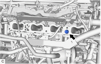
2. REMOVE PCV VALVE (VENTILATION VALVE SUB-ASSEMBLY)
| (a) Remove the PCV valve (ventilation valve sub-assembly) from the cylinder head sub-assembly. |
|
READ NEXT:
 Inspection
INSPECTION PROCEDURE 1. INSPECT PCV VALVE (VENTILATION VALVE SUB-ASSEMBLY) (a) Install a hose to the PCV valve (ventilation valve sub-assembly). (b) Check the PCV valve (ventilation valve sub-assembly
Installation
INSTALLATION CAUTION / NOTICE / HINT NOTICE: This procedure includes the installation of small-head bolts. Refer to Small-Head Bolts of Basic Repair Hint to identify the small-head bolts. Click here
Purge Valve
ComponentsCOMPONENTS ILLUSTRATION *1 PURGE VALVE (PURGE VSV) *2 NO. 1 FUEL VAPOR FEED HOSE *3 NO. 2 FUEL VAPOR FEED HOSE - - N*m (kgf*cm, ft.*lbf): Specified torque - -
SEE MORE:
Diagnosis System
DIAGNOSIS SYSTEM DESCRIPTION (a) The battery ECU assembly has a self-diagnosis system. If the computer, hybrid control system, or a component is not working properly, the ECU records the conditions that relate to the fault. The ECU also illuminates the master warning light in the combination meter a
ABS does not Operate
DESCRIPTION When the electronically controlled brake system is operating, as the input piston and output piston are not directly connected, the kickback of the brake pedal is minimal during ABS operation and the driver may not notice that ABS operated. CAUTION / NOTICE / HINT NOTICE: After replacing
