Lexus ES: Purge Valve
Components
COMPONENTS
ILLUSTRATION
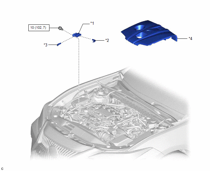
| *1 | PURGE VALVE (PURGE VSV) | *2 | NO. 1 FUEL VAPOR FEED HOSE |
| *3 | NO. 2 FUEL VAPOR FEED HOSE | - | - |
.png) | N*m (kgf*cm, ft.*lbf): Specified torque | - | - |
Removal
REMOVAL
PROCEDURE
1. REMOVE NO. 1 ENGINE COVER SUB-ASSEMBLY
Click here .gif)
2. REMOVE PURGE VALVE (PURGE VSV)
| (a) Disconnect the purge valve (purge VSV) connector. |
|
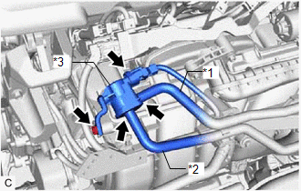
(b) Disconnect the No. 1 fuel vapor feed hose from the purge valve (purge VSV).
(c) Disconnect the No. 2 fuel vapor feed hose from the purge valve (purge VSV).
(d) Remove the bolt and purge valve (purge VSV) from the intake manifold.
Inspection
INSPECTION
PROCEDURE
1. INSPECT PURGE VALVE (PURGE VSV)
(a) Measure the resistance according to the value(s) in the table below.
Standard Resistance:
| Tester Connection | Condition | Specified Condition |
|---|---|---|
| 1 - 2 | 20°C (68°F) | 23 to 26 Ω |
If the result is not as specified, replace the purge valve (purge VSV).
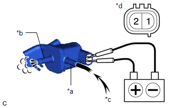
| (b) Apply battery voltage between the terminals of the purge valve (purge VSV) and check that the following occurs when blowing air into the port (E). OK:
If the result is not as specified, replace the purge valve (purge VSV). |
|
Installation
INSTALLATION
PROCEDURE
1. INSTALL PURGE VALVE (PURGE VSV)
| (a) Install the purge valve (purge VSV) to the intake manifold with the bolt. Torque: 10 N·m {102 kgf·cm, 7 ft·lbf} |
|
.png)
(b) Connect the No. 2 fuel vapor feed hose to the purge valve (purge VSV).
(c) Connect the No. 1 fuel vapor feed hose to the purge valve (purge VSV).
(d) Connect the purge valve (purge VSV) connector.
2. INSTALL NO. 1 ENGINE COVER SUB-ASSEMBLY
Click here .gif)
READ NEXT:
 Vacuum Sensor
ComponentsCOMPONENTS ILLUSTRATION *1 E.F.I. VACUUM SENSOR ASSEMBLY (MANIFOLD ABSOLUTE PRESSURE SENSOR) *2 VACUUM HOSE N*m (kgf*cm, ft.*lbf): Specified torque - - RemovalREMOV
SEE MORE:
Terminals Of Ecu
TERMINALS OF ECU CHECK WINDSHIELD WIPER MOTOR ASSEMBLY (a) Disconnect the A38 windshield wiper motor assembly connector. (b) Measure the voltage and resistance on the wire harness side connector according to the value(s) in the table below. Terminal No. (Symbol) Wiring Color Terminal Descrip
Inspection
INSPECTION PROCEDURE 1. INSPECT TILT AND TELESCOPIC SWITCH (a) Remove the tilt and telescopic switch. Click here (b) Measure the resistance according to the value(s) in the table below. Standard Resistance: Tester Connection Condition Specified Condition 1 (VC) - 3 (MSW) Tilt up
