Lexus ES: Removal
REMOVAL
PROCEDURE
1. REMOVE NO. 1 INSTRUMENT PANEL UNDER COVER SUB-ASSEMBLY
Click here .gif)
2. REMOVE ACCELERATOR PEDAL(W/SENSOR) ROD ASSEMBLY
NOTICE:
- Avoid physical shock to the accelerator pedal sensor assembly.
- Do not disassemble the accelerator pedal sensor assembly.
- The accelerator pedal sensor assembly does not require lubrication.
- Do not apply oil or other lubricants to the accelerator pedal sensor assembly. If applied, the accelerator pedal sensor assembly must be replaced.
| (a) Disconnect the accelerator pedal sensor assembly connector. |
|
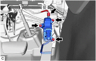
(b) Remove the 3 nuts and disconnect the rod of the accelerator pedal sensor assembly from the accelerator pedal assembly to remove the accelerator pedal sensor assembly.
NOTICE:
If the accelerator pedal sensor assembly has been struck or dropped, replace it.
3. REMOVE ACCELERATOR PEDAL PAD
| (a) Disengage the 4 claws and remove the accelerator pedal pad from the accelerator pedal assembly. |
|
.png)
4. REMOVE ACCELERATOR PEDAL ASSEMBLY
| (a) Remove the 2 bolts. |
|
.png)
(b) Push the accelerator pedal assembly in the direction indicated by the arrow (1) shown in the illustration to disengage the claw.
.png)
| *a | Vehicle Body |
.png) | Remove in this Direction (1) |
.png) | Remove in this Direction (2) |
(c) Pull the accelerator pedal assembly in the direction indicated by the arrow (2) shown in the illustration to remove it.
READ NEXT:
 Installation
INSTALLATION PROCEDURE 1. INSTALL ACCELERATOR PEDAL ASSEMBLY (a) Engage the claw to install the accelerator pedal assembly. (b) Install the 2 bolts. Torque: 7.5 N·m {76 kgf·cm, 66 in
Components
COMPONENTS ILLUSTRATION *1 FRONT WHEEL OPENING EXTENSION PAD LH *2 FRONT WHEEL OPENING EXTENSION PAD RH *3 NO. 1 ENGINE UNDER COVER *4 NO. 2 ENGINE UNDER COVER ASSEMBLY N*m
SEE MORE:
Front Right Sensor Malfunction (C1AE4)
DESCRIPTION The front corner ultrasonic sensor RH is installed to the front bumper. The clearance warning ECU assembly detects obstacles based on signals received from the front corner ultrasonic sensor RH. If the front corner ultrasonic sensor RH has an open circuit or other malfunction, it will no
Front Passenger Side Power Window does not Operate with Front Passenger Side Power Window Switch
DESCRIPTION When the power switch is on (IG), the power window regulator motor assembly (for front passenger door) is operated by the power window regulator switch assembly. The power window regulator motor assembly (for front passenger door) has motor, regulator, and ECU functions. WIRING DIAGRAM
