Lexus ES: Removal
REMOVAL
CAUTION / NOTICE / HINT
The necessary procedures (adjustment, calibration, initialization or registration) that must be performed after parts are removed and installed, or replaced during engine unit removal/installation are shown below.
Necessary Procedure After Parts Removed/Installed/Replaced| Replaced Part or Performed Procedure | Necessary Procedure | Effect/Inoperative Function when Necessary Procedure not Performed | Link |
|---|---|---|---|
| Battery terminal is disconnected/reconnected | Perform steering sensor zero point calibration | Lane Control System | |
| Pre-collision System | |||
| Parking Support Brake System*1 | |||
| Lighting System | |||
| Memorize steering angle neutral point | Parking Assist Monitor System | | |
| Panoramic View Monitor System | | ||
| Initialize power trunk lid system | Power Trunk Lid System | | |
| Replacement of ECM | Vehicle Identification Number (VIN) registration | MIL comes on | |
| ECU communication ID registration (Immobiliser system) | Engine start function | | |
| Inspection after repair |
| |
| Replacement of automatic transaxle assembly |
|
| for Initialization: for Registration: |
| Replacement of ECM (If transaxle compensation code read from ECM) |
| ||
| Replacement of ECM (If transaxle compensation code not read from ECM) |
| ||
| Replacement of ECM | Code registration (Smart access system with push-button start (for Start Function, Gasoline Model) |
| |
| Replacement of automatic transaxle fluid | ATF thermal degradation estimate reset | The value of the Data List item "ATF Thermal Degradation Estimate" is not estimated correctly | |
| Suspension, tires, etc. (The vehicle height changes because of suspension or tire replacement) | Rear television camera assembly optical axis adjustment (Back camera position setting) | Parking assist monitor system | for Initialization: for Calibration: |
| Perform headlight ECU sub-assembly LH initialization | Lighting system | | |
| Front wheel alignment adjustment |
|
| |
| Front television camera view adjustment | Panoramic View Monitor System | for Initialization for Calibration |
| Replacement of front bumper assembly |
|
| |
-
*1: When performing learning using the Techstream.
Click here
.gif)
- *2: Not necessary when ECM replaced with new one
NOTICE:
- After the engine switch is turned off, the radio receiver assembly records various types of memory and settings. As a result, after turning the engine switch off, make sure to wait at least 85 seconds before disconnecting the cable from the negative (-) battery terminal. (for Audio and Visual System)
- After the engine switch is turned off, the radio receiver assembly records various types of memory and settings. As a result, after turning the engine switch off, make sure to wait at least 85 seconds before disconnecting the cable from the negative (-) battery terminal. (for Navigation System)
PROCEDURE
1. REMOVE KNOCK CONTROL SENSOR
Click here
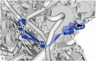
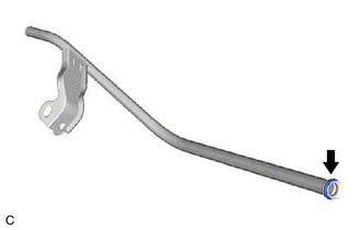
2. REMOVE SENSOR WIRE
| (a) Disengage the 2 clamps and remove the bolt and sensor wire. |
|
3. REMOVE IGNITION COIL ASSEMBLY
Click here
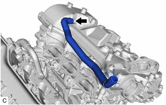
4. REMOVE VACUUM PUMP ASSEMBLY
-
for TMMK Made:
Click here
-
for TMC Made:
Click here
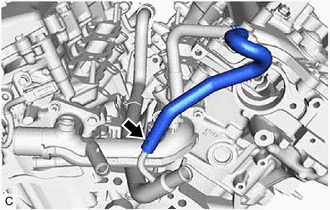
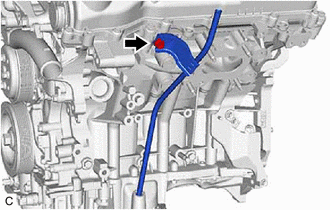
5. REMOVE NO. 3 WATER BY-PASS HOSE
| (a) Slide the clip and remove the No. 3 water by-pass hose from the water inlet pipe. |
|
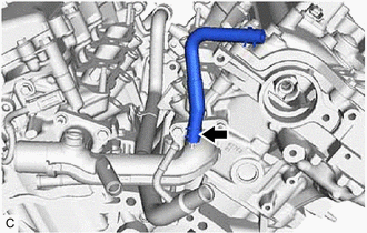
6. REMOVE NO. 2 WATER BY-PASS HOSE
| (a) Slide the clip and remove the No. 2 water by-pass hose from the water outlet. |
|
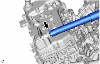
7. REMOVE VENTILATION HOSE
| (a) Slide the clip and remove the ventilation hose from the PCV valve (ventilation valve sub-assembly). |
|
8. REMOVE NO. 2 VENTILATION HOSE
| (a) Slide the clip and remove the No. 2 ventilation hose from the cylinder head cover sub-assembly. |
|
9. REMOVE V-RIBBED BELT
Click here
10. REMOVE GENERATOR ASSEMBLY
Click here
11. REMOVE COMPRESSOR ASSEMBLY WITH MAGNETIC CLUTCH
Click here
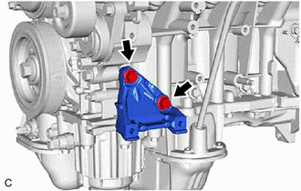
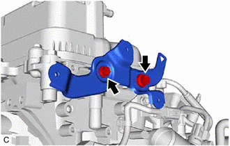
12. REMOVE NO. 1 COMPRESSOR MOUNTING BRACKET
| (a) Remove the 2 bolts and No. 1 compressor mounting bracket from the cylinder block sub-assembly. |
|
13. REMOVE NO. 2 IDLER PULLEY SUB-ASSEMBLY
Click here
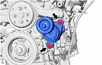
14. REMOVE V-RIBBED BELT TENSIONER ASSEMBLY
| (a) Remove the 2 bolts and V-ribbed belt tensioner assembly. |
|
15. REMOVE WATER PUMP PULLEY
Click here
16. REMOVE ENGINE OIL LEVEL DIPSTICK GUIDE
(a) Remove the engine oil level dipstick from the engine oil level dipstick guide.
| (b) Remove the bolt and engine oil level dipstick guide from the camshaft housing sub-assembly LH and oil pan sub-assembly. |
|
| (c) Remove the engine oil level dipstick guide O-ring from the engine oil level dipstick guide. |
|
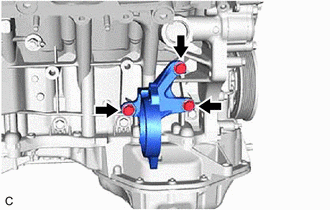
17. REMOVE DRIVE SHAFT BEARING BRACKET
| (a) Remove the 3 bolts and drive shaft bearing bracket from the cylinder block sub-assembly. |
|
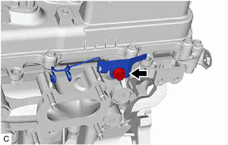
18. REMOVE WIRE HARNESS CLAMP BRACKET
| (a) Remove the bolt and wire harness clamp bracket from the camshaft housing sub-assembly LH. |
|
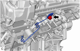
| (b) Remove the bolt and wire harness clamp bracket from the camshaft housing sub-assembly. |
|
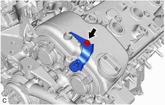
19. REMOVE WATER FILLER BRACKET
| (a) Remove the 2 bolts and water filler bracket from the camshaft housing sub-assembly LH. |
|
20. REMOVE ENGINE COVER BRACKET
| (a) Remove the bolt and engine cover bracket from the cylinder head cover sub-assembly LH. |
|
READ NEXT:
 Disassembly
DISASSEMBLY PROCEDURE 1. REMOVE OIL FILLER CAP SUB-ASSEMBLY (a) Remove the oil filler cap sub-assembly from the cylinder head cover sub-assembly LH. (b) Remove the oil filler cap gas
Inspection
INSPECTION PROCEDURE 1. INSPECT NO. 1 VALVE ROCKER ARM SUB-ASSEMBLY (a) Turn the roller by hand to check that it turns smoothly. HINT: If the roller does not turn smoothly, replace the No. 1 valve
Reassembly
REASSEMBLY PROCEDURE 1. INSTALL WATER INLET PIPE (a) Install the water inlet pipe with the 2 bolts. Torque: 10 N·m {102 kgf·cm, 7 ft·lbf} 2. INSTALL NO. 2 CYLINDER HEAD GASKET Click
SEE MORE:
Camshaft Position "A" - Timing Over-Advanced or System Performance Bank 1 (P001100,P001200,P002100,P002200)
DESCRIPTION Refer to DTC P001013. Click here DTC No. Detection Item DTC Detection Condition Trouble Area MIL Memory Note P001100 Camshaft Position "A" - Timing Over-Advanced or System Performance Bank 1 Intake valve timing is stuck at a certain value when in the advance rang
Communication Error From Clearance Sonar ECU to VSC (C164B)
DESCRIPTION The electronically controlled brake system receives parking support brake system information from the clearance warning ECU assembly via CAN communication. When it is determined that there is a communication error between the skid control ECU and clearance warning ECU assembly, DTC C164B
