Lexus ES: Removal
REMOVAL
CAUTION / NOTICE / HINT
The necessary procedures (adjustment, calibration, initialization or registration) that must be performed after parts are removed and installed, or replaced during cylinder head gasket removal/installation are shown below.
Necessary Procedure After Parts Removed/Installed/Replaced| Replaced Part or Performed Procedure | Necessary Procedure | Effect/Inoperative Function when Necessary Procedure not Performed | Link |
|---|---|---|---|
| Battery terminal is disconnected/reconnected | Perform steering sensor zero point calibration | Lane Control System | |
| Pre-collision System | |||
| Parking Support Brake System*1 | |||
| Lighting System | |||
| Memorize steering angle neutral point | Parking Assist Monitor System | | |
| Panoramic View Monitor System | | ||
| Initialize power trunk lid system | Power Trunk Lid System | | |
| Replacement of ECM | Vehicle Identification Number (VIN) registration | MIL comes on | |
| ECU communication ID registration (Immobiliser system) | Engine start function | | |
| Inspection after repair |
| |
| Replacement of automatic transaxle assembly |
|
| for Initialization: for Registration: |
| Replacement of ECM (If transaxle compensation code read from ECM) |
| ||
| Replacement of ECM (If transaxle compensation code not read from ECM) |
| ||
| Replacement of ECM | Code registration (Smart access system with push-button start (for Start Function, Gasoline Model) |
| |
| Replacement of automatic transaxle fluid | ATF thermal degradation estimate reset | The value of the Data List item "ATF Thermal Degradation Estimate" is not estimated correctly | |
| Suspension, tires, etc. (The vehicle height changes because of suspension or tire replacement) | Rear television camera assembly optical axis adjustment (Back camera position setting) | Parking assist monitor system | for Initialization: for Calibration: |
| Perform headlight ECU sub-assembly LH initialization | Lighting system | | |
| Front wheel alignment adjustment |
|
| |
| Front television camera view adjustment | Panoramic View Monitor System | for Initialization for Calibration |
| Replacement of front bumper assembly |
|
| |
-
*1: When performing learning using the Techstream.
Click here
.gif)
- *2: Not necessary when ECM replaced with new one
NOTICE:
- After the engine switch is turned off, the radio receiver assembly records various types of memory and settings. As a result, after turning the engine switch off, make sure to wait at least 85 seconds before disconnecting the cable from the negative (-) battery terminal. (for Audio and Visual System)
- After the engine switch is turned off, the radio receiver assembly records various types of memory and settings. As a result, after turning the engine switch off, make sure to wait at least 85 seconds before disconnecting the cable from the negative (-) battery terminal. (for Navigation System)
PROCEDURE
1. INSTALL ENGINE ASSEMBLY TO ENGINE STAND
Click here
2. REMOVE ENGINE HANGERS
Click here
3. REMOVE KNOCK CONTROL SENSOR
Click here
4. REMOVE IGNITION COIL ASSEMBLY
Click here
5. REMOVE VACUUM PUMP ASSEMBLY
-
for TMMK Made:
Click here
-
for TMC Made:
Click here
6. REMOVE V-RIBBED BELT
Click here
7. REMOVE GENERATOR ASSEMBLY
Click here
8. REMOVE COMPRESSOR ASSEMBLY WITH MAGNETIC CLUTCH
Click here
9. REMOVE NO. 2 IDLER PULLEY SUB-ASSEMBLY
Click here
10. REMOVE V-RIBBED BELT TENSIONER ASSEMBLY
Click here
11. REMOVE WATER PUMP PULLEY
Click here
12. REMOVE ENGINE OIL LEVEL DIPSTICK GUIDE
Click here
13. REMOVE WIRE HARNESS CLAMP BRACKET
Click here
14. REMOVE WATER FILLER BRACKET
Click here
15. REMOVE CRANKSHAFT PULLEY
Click here
16. REMOVE FRONT NO. 1 ENGINE MOUNTING BRACKET LH
Click here
17. DISCONNECT WATER BY-PASS HOSE
Click here
18. REMOVE WATER INLET WITH THERMOSTAT SUB-ASSEMBLY
Click here
19. REMOVE CAMSHAFT TIMING OIL CONTROL SOLENOID ASSEMBLY (for Intake Side of Bank 1)
Click here
20. REMOVE CAMSHAFT TIMING OIL CONTROL SOLENOID ASSEMBLY (for Exhaust Side of Bank 1)
Click here
21. REMOVE CAMSHAFT TIMING OIL CONTROL SOLENOID ASSEMBLY (for Exhaust Side of Bank 2)
Click here
22. REMOVE CAMSHAFT TIMING OIL CONTROL SOLENOID ASSEMBLY (for Intake Side of Bank 2)
Click here
23. REMOVE VVT SENSOR (for Intake Side of Bank 1)
Click here
24. REMOVE VVT SENSOR (for Exhaust Side of Bank 1)
Click here
25. REMOVE VVT SENSOR (for Intake Side of Bank 2)
Click here
26. REMOVE VVT SENSOR (for Exhaust Side of Bank 2)
Click here
27. REMOVE CRANKSHAFT POSITION SENSOR PROTECTOR
Click here
28. REMOVE SENSOR WIRE
Click here
29. REMOVE CYLINDER HEAD COVER SUB-ASSEMBLY
Click here
30. REMOVE CYLINDER HEAD COVER SUB-ASSEMBLY LH
Click here
31. REMOVE SPARK PLUG TUBE GASKET
Click here
32. REMOVE NO. 2 OIL PAN SUB-ASSEMBLY
Click here
33. REMOVE OIL STRAINER SUB-ASSEMBLY
Click here
34. REMOVE OIL PAN SUB-ASSEMBLY
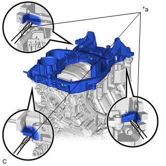
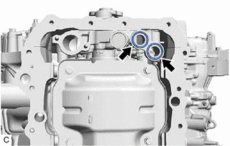
| (a) Remove the 16 bolts and 2 nuts from the oil pan sub-assembly. NOTICE: Make sure to clean the bolts and stud bolts and check the threads for cracks or other damage. |
|
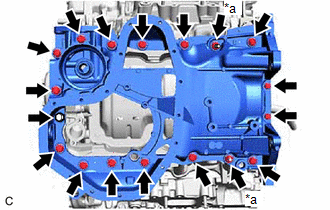
| (b) Remove the oil pan sub-assembly by prying between the oil pan sub-assembly and timing chain cover assembly or cylinder block sub-assembly with a screwdriver wrapped with protective tape. NOTICE: Be careful not to damage the contact surfaces of the cylinder block sub-assembly, timing chain cover assembly and oil pan sub-assembly. |
|
| (c) Remove the 2 oil pan gaskets from the timing chain cover assembly. |
|
35. REMOVE TIMING CHAIN COVER ASSEMBLY
Click here
36. REMOVE TIMING CHAIN CASE OIL SEAL
Click here
37. SET NO. 1 CYLINDER TO TDC (COMPRESSION)
Click here
38. REMOVE NO. 1 CHAIN TENSIONER ASSEMBLY
Click here
39. REMOVE CHAIN TENSIONER SLIPPER
Click here
40. REMOVE CHAIN SUB-ASSEMBLY
Click here
41. REMOVE CAMSHAFT TIMING GEAR ASSEMBLY, CAMSHAFT TIMING EXHAUST GEAR ASSEMBLY AND NO. 2 CHAIN SUB-ASSEMBLY (for Bank 1)
Click here
42. REMOVE NO. 2 CHAIN TENSIONER ASSEMBLY
Click here
43. REMOVE CAMSHAFT BEARING CAP (for Bank 1)
Click here
44. REMOVE CAMSHAFT
Click here
45. REMOVE NO. 2 CAMSHAFT
Click here
46. REMOVE CAMSHAFT HOUSING SUB-ASSEMBLY
Click here
47. REMOVE CAMSHAFT TIMING GEAR ASSEMBLY, CAMSHAFT TIMING EXHAUST GEAR ASSEMBLY AND NO. 2 CHAIN SUB-ASSEMBLY (for Bank 2)
Click here
48. REMOVE NO. 3 CHAIN TENSIONER ASSEMBLY
Click here
49. REMOVE CAMSHAFT BEARING CAP (for Bank 2)
Click here
50. REMOVE NO. 3 CAMSHAFT SUB-ASSEMBLY
Click here
51. REMOVE NO. 4 CAMSHAFT SUB-ASSEMBLY
Click here
52. REMOVE CAMSHAFT HOUSING SUB-ASSEMBLY LH
Click here
53. REMOVE SENSOR WIRE
Click here
54. REMOVE NO. 1 CHAIN VIBRATION DAMPER
Click here
55. REMOVE NO. 2 CHAIN VIBRATION DAMPER
Click here
56. REMOVE NO. 1 VALVE ROCKER ARM SUB-ASSEMBLY
Click here
57. REMOVE VALVE LASH ADJUSTER ASSEMBLY
Click here
58. REMOVE VALVE STEM CAP
Click here
59. REMOVE WATER OUTLET
Click here
60. REMOVE CYLINDER HEAD SUB-ASSEMBLY
Click here
61. REMOVE CYLINDER HEAD GASKET
(a) Remove the cylinder head gasket from the cylinder block sub-assembly.
62. REMOVE CYLINDER HEAD LH
Click here
63. REMOVE NO. 2 CYLINDER HEAD GASKET
(a) Remove the No. 2 cylinder head gasket from the cylinder block sub-assembly.
64. INSPECT CYLINDER HEAD SET BOLT
Click here
READ NEXT:
 Installation
INSTALLATION PROCEDURE 1. INSTALL NO. 2 CYLINDER HEAD GASKET (a) Place a new No. 2 cylinder head gasket on the cylinder block sub-assembly as shown in the illustration. *a Lot No. Front o
Drive Belt
PrecautionPRECAUTION NOTICE:
Do not apply or add any oil or grease to the belt tensioner to prevent abnormal noises from the belt tensioner pulley, belt squealing, etc.
Do not allow oil or
SEE MORE:
Inspection
INSPECTION PROCEDURE 1. INSPECT FUEL LID LOCK WITH MOTOR ASSEMBLY (a) Check the operation of the fuel lid lock with motor assembly (motor operation). (1) Apply auxiliary battery voltage to the fuel lid lock with motor assembly connector, and check the operation of the fuel lid lock with motor assemb
ECM/PCM Engine Off Timer Performance Signal Invalid (P261029,P261093)
DTC SUMMARY DTC No. Detection Item DTC Detection Condition Trouble Area MIL Memory Note P261029 ECM/PCM Engine Off Timer Performance Signal Invalid ECM internal malfunction ECM Comes on DTC stored SAE Code: P2610 P261093 ECM/PCM Engine Off Timer Performance No Op
