Lexus ES: Drive Motor "A" Temperature Sensor Voltage Out of Range (P0A2A1C,P0A2A1F)
DTC SUMMARY
MALFUNCTION DESCRIPTION
These DTCs are stored when the motor temperature sensor output is abnormal. The cause of this malfunction may be one of the following:
- Internal motor temperature sensor malfunction
- Open or short in motor temperature sensor
- The connectors are not connected properly
- Foreign matter or water on the connector terminals
- Open or short in wire harness
HINT:
If any of these DTCs are stored, the motor temperature sensor is malfunctioning and the self-protection function may not operate. Therefore under certain high load driving condition, the temperature of the motor (MG2) becomes high. If the self-protection function does not operate, the motor (MG2) may malfunction and cause the vehicle to enter fail-safe mode.
DESCRIPTION
Refer to the description for DTC P0A2A11.
Click here .gif)
| DTC No. | Detection Item | DTC Detection Condition | Trouble Area | MIL | Warning Indicate |
|---|---|---|---|---|---|
| P0A2A1C | Drive Motor "A" Temperature Sensor Voltage Out of Range | After a long soak, the value of the motor (MG2) temperature sensor is different from the value of the other temperature sensors. (2 trip detection logic) |
| Comes on | Master Warning Light: Comes on |
| P0A2A1F | Drive Motor "A" Temperature Sensor Circuit Intermittent | Sudden change in motor temperature sensor output or hunting: Unusual sudden change in motor temperature sensor output occurs and offset condition continues for a certain period of time, or unusual change in motor temperature sensor output occurs repeatedly. (1 trip detection logic) |
| Comes on | Master Warning Light: Comes on |
| DTC No. | Data List |
|---|---|
| P0A2A1C |
|
| P0A2A1F | Motor Temperature |
MONITOR DESCRIPTION
If the hybrid vehicle control ECU detects a malfunction of the motor temperature sensor, it will illuminate the MIL and store a DTC.
MONITOR STRATEGY
| Related DTCs | P0A2B (INF P0A2A1C): Drive Motor "A" Temperature Sensor Circuit Range/Performance P0A2E (INF P0A2A1F): Drive Motor "A" Temperature Sensor Circuit Intermittent |
| Required sensors/components | Motor temperature sensor |
| Frequency of operation | Continuous |
| Duration | TMC's intellectual property |
| MIL operation | 2 driving cycle / 1 driving cycle |
| Sequence of operation | None |
TYPICAL ENABLING CONDITIONS
| The monitor will run whenever the following DTCs are not stored | TMC's intellectual property |
| Other conditions belong to TMC's intellectual property | - |
TYPICAL MALFUNCTION THRESHOLDS
| TMC's intellectual property | - |
COMPONENT OPERATING RANGE
| Hybrid vehicle control ECU | DTC P0A2B (INF P0A2A1C) is not detected DTC P0A2E (INF P0A2A1F) is not detected |
CONFIRMATION DRIVING PATTERN
HINT:
-
After repair has been completed, clear the DTC and then check that the vehicle has returned to normal by performing the following All Readiness check procedure.
Click here
-
When clearing the permanent DTCs, refer to the "CLEAR PERMANENT DTC" procedure.
Click here
- Connect the Techstream to the DLC3.
- Turn the power switch on (IG) and turn the Techstream on.
- Clear the DTCs (even if no DTCs are stored, perform the clear DTC procedure).
- Turn the power switch off.
- Leave the vehicle as is for 5 hours or more and then check the values of the Data List items "Generator Temperature", "Motor Temperature" and "Inverter Coolant Water Temperature". [*1]
-
Turn the power switch on (IG) and turn the Techstream on. [*2]
HINT:
[*1] to [*2]: Normal judgment procedure.
The normal judgment procedure is used to complete DTC judgment and also used when clearing permanent DTCs.
- Enter the following menus: Powertrain / Hybrid Control / Utility / All Readiness.
-
Check the DTC judgment result.
HINT:
- If the judgment result shows NORMAL, the system is normal.
- If the judgment result shows ABNORMAL, the system has a malfunction.
- If the judgment result shows INCOMPLETE or N/A, perform the normal judgment procedure again.
- Connect the Techstream to the DLC3.
- Turn the power switch on (IG) and turn the Techstream on.
- Clear the DTCs (even if no DTCs are stored, perform the clear DTC procedure).
- Turn the power switch off and wait for 2 minutes or more.
- Turn the power switch on (IG) and turn the Techstream on.
-
With power switch on (IG) and wait for 5 seconds or more. [*1]
HINT:
[*1] : Normal judgment procedure.
The normal judgment procedure is used to complete DTC judgment and also used when clearing permanent DTCs.
- Enter the following menus: Powertrain / Hybrid Control / Utility / All Readiness.
-
Check the DTC judgment result.
HINT:
- If the judgment result shows NORMAL, the system is normal.
- If the judgment result shows ABNORMAL, the system has a malfunction.
- If the judgment result shows INCOMPLETE or N/A, perform the normal judgment procedure again.
WIRING DIAGRAM
Refer to the wiring diagram for DTC P0A2A11.
Click here
PROCEDURE
| 1. | CHECK DTC OUTPUT (ENGINE) |
(a) Connect the Techstream to the DLC3.
(b) Turn the power switch on (IG).
(c) Enter the following menus: Powertrain / Engine / Trouble Codes.
Powertrain > Engine > Trouble Codes(d) Check for DTCs.
| Result | Proceed to |
|---|---|
| No DTCs are output, or DTCs except the ones in the table below are also output | A |
| Any of the following DTCs are also output | B |
| Relevant DTC | |
|---|---|
| P261029 | ECM/PCM Engine Off Timer Performance Signal Invalid |
(e) Turn the power switch off.
| B | .gif) | GO TO DTC CHART (SFI SYSTEM) |
|
.gif)
| 2. | CHECK DTC OUTPUT (HYBRID CONTROL) |
(a) Connect the Techstream to the DLC3.
(b) Turn the power switch on (IG).
(c) Enter the following menus: Powertrain / Hybrid Control / Trouble Codes.
(d) Check for DTCs.
Powertrain > Hybrid Control > Trouble Codes| Result | Proceed to |
|---|---|
| No DTCs are output, or DTCs except the ones in the table below are also output | A |
| Any of the following DTCs are also output | B |
| Relevant DTC | |
|---|---|
| P0A2A11 | Drive Motor "A" Temperature Sensor Circuit Short to Ground |
| P0A2A15 | Drive Motor "A" Temperature Sensor Circuit Short to Auxiliary Battery or Open |
(e) Turn the power switch off.
| B | | GO TO DTC CHART (HYBRID CONTROL SYSTEM) |
|
| 3. | CHECK CONNECTOR CONNECTION CONDITION (HYBRID VEHICLE CONTROL ECU CONNECTOR) |
Click here
| Result | Proceed to |
|---|---|
| OK | A |
| NG (The connector is not connected securely.) | B |
| NG (The terminals are not making secure contact or are deformed, or water or foreign matter exists in the connector.) | C |
| B | | CONNECT SECURELY |
| C | | REPAIR OR REPLACE HARNESS OR CONNECTOR |
|
| 4. | CHECK HARNESS AND CONNECTOR (MOTOR TEMPERATURE SENSOR - HYBRID VEHICLE CONTROL ECU) |
(a) Disconnect the A32 hybrid vehicle control ECU connector.
| (b) Measure the resistance according to the value(s) in the table below. Standard Resistance:
|
|
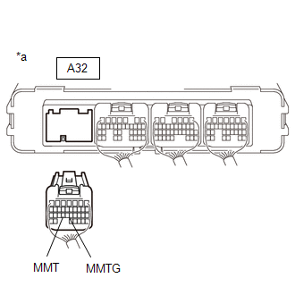
(c) Reconnect the A32 hybrid vehicle control ECU connector.
| NG | | GO TO STEP 9 |
|
| 5. | CHECK CONNECTOR CONNECTION CONDITION (INTERMEDIATE CONNECTOR) |
Click here
| Result | Proceed to |
|---|---|
| OK | A |
| NG (The connector is not connected securely.) | B |
| NG (The terminals are not making secure contact or are deformed, or water or foreign matter exists in the connector.) | C |
| B | | CONNECT SECURELY |
| C | | REPAIR OR REPLACE HARNESS OR CONNECTOR |
|
| 6. | CHECK HARNESS AND CONNECTOR (HYBRID VEHICLE CONTROL ECU - NO. 1 ENGINE ROOM RELAY BLOCK AND NO. 1 JUNCTION BLOCK ASSEMBLY) |
(a) Disconnect the CA3 No. 1 engine room relay block and No. 1 junction block assembly connector.
(b) Disconnect the A32 hybrid vehicle control ECU connector.
(c) Measure the resistance according to the value(s) in the table below.
HINT:
When performing the measurement, lightly jiggle the wire harness up and down and left and right and confirm that the resistance does not fluctuate.
Standard Resistance (Check for Open):
| Tester Connection | Condition | Specified Condition |
|---|---|---|
| CA3-4 (MMT) - A32-24 (MMT) | Power switch off | Below 1 Ω |
| CA3-16 (MMTG) - A32-23 (MMTG) | Power switch off | Below 1 Ω |
Standard Resistance (Check for Short):
| Tester Connection | Condition | Specified Condition |
|---|---|---|
| CA3-4 (MMT) or A32-24 (MMT) - Body ground and other terminals | Power switch off | 10 kΩ or higher |
| CA3-16 (MMTG) or A32-23 (MMTG) - Body ground and other terminals | Power switch off | 10 kΩ or higher |
(d) Reconnect the A32 hybrid vehicle control ECU connector.
(e) Reconnect the CA3 No. 1 engine room relay block and No. 1 junction block assembly connector.
| NG | | REPAIR OR REPLACE HARNESS OR CONNECTOR |
|
| 7. | CHECK CONNECTOR CONNECTION CONDITION (MOTOR TEMPERATURE SENSOR CONNECTOR) |
Click here
| Result | Proceed to |
|---|---|
| OK | A |
| NG (The connector is not connected securely.) | B |
| NG (The terminals are not making secure contact or are deformed, or water or foreign matter exists in the connector.) | C |
| B | | CONNECT SECURELY |
| C | | REPAIR OR REPLACE HARNESS OR CONNECTOR |
|
| 8. | CHECK HARNESS AND CONNECTOR (NO. 1 ENGINE ROOM RELAY BLOCK AND NO. 1 JUNCTION BLOCK ASSEMBLY - MOTOR TEMPERATURE SENSOR) |
(a) Disconnect the C90 motor temperature sensor connector.
(b) Disconnect the CA3 No. 1 engine room relay block and No. 1 junction block assembly connector.
(c) Measure the resistance according to the value(s) in the table below.
HINT:
When performing the measurement, lightly jiggle the wire harness up and down and left and right and confirm that the resistance does not fluctuate.
Standard Resistance (Check for Open):
| Tester Connection | Condition | Specified Condition |
|---|---|---|
| CA3-4 (MMT) - C90-1 (MMT) | Power switch off | Below 1 Ω |
| CA3-16 (MMTG) - C90-2 (MMTG) | Power switch off | Below 1 Ω |
Standard Resistance (Check for Short):
| Tester Connection | Condition | Specified Condition |
|---|---|---|
| CA3-4 (MMT) or C90-1 (MMT) - Body ground and other terminals | Power switch off | 10 kΩ or higher |
| CA3-16 (MMTG) or C90-2 (MMTG) - Body ground and other terminals | Power switch off | 10 kΩ or higher |
(d) Reconnect the CA3 No. 1 engine room relay block and No. 1 junction block assembly connector.
(e) Reconnect the C90 motor temperature sensor connector.
| OK | | REPLACE HYBRID VEHICLE TRANSAXLE ASSEMBLY |
| NG | | REPAIR OR REPLACE HARNESS OR CONNECTOR |
| 9. | INSPECT HYBRID VEHICLE TRANSAXLE ASSEMBLY (MOTOR TEMPERATURE SENSOR) |
(a) Disconnect the CA3 No. 1 engine room relay block and No. 1 junction block assembly connector.
(b) Measure the resistance according to the value(s) in the table below.
Standard Resistance:
| Tester Connection | Condition | Specified Condition |
|---|---|---|
| CA3-4 (MMT) - CA3-16 (MMTG) | Power switch off | 0.3443 to 1446 kΩ |
(c) Reconnect the CA3 No. 1 engine room relay block and No. 1 junction block assembly connector.
| OK | | REPAIR OR REPLACE HARNESS OR CONNECTOR (HYBRID VEHICLE CONTROL ECU - NO. 1 ENGINE ROOM RELAY BLOCK AND NO. 1 JUNCTION BLOCK ASSEMBLY) |
|
| 10. | INSPECT HYBRID VEHICLE TRANSAXLE ASSEMBLY (MOTOR TEMPERATURE SENSOR) |
Click here
| OK | | REPAIR OR REPLACE HARNESS OR CONNECTOR (NO. 1 ENGINE ROOM RELAY BLOCK AND NO. 1 JUNCTION BLOCK ASSEMBLY - MOTOR TEMPERATURE SENSOR) |
| NG | | REPLACE HYBRID VEHICLE TRANSAXLE ASSEMBLY |
READ NEXT:
 Generator Temperature Sensor Circuit Short to Ground (P0A3611,P0A3615)
DTC SUMMARY MALFUNCTION DESCRIPTION These DTCs are stored when the generator temperature sensor output is abnormal. The cause of this malfunction may be one of the following: Hybrid vehicle control E
Generator Temperature Sensor Voltage Out of Range (P0A361C,P0A361F)
DTC SUMMARY MALFUNCTION DESCRIPTION These DTCs are stored when the generator temperature sensor output is abnormal. The cause of this malfunction may be one of the following: Generator temperature se
Hybrid/EV Battery Cooling Fan 1 Control Circuit High (P0A8100,P0A8115)
DESCRIPTION Refer to the description for DTC P0A8111. Click here DTC No. Detection Item DTC Detection Condition Trouble Area MIL Warning Indicate P0A8100 Hybrid/EV Battery Cooling
SEE MORE:
Problem Symptoms Table
PROBLEM SYMPTOMS TABLE HINT:
Use the table below to help determine the cause of problem symptoms. If multiple suspected areas are listed, the potential causes of the symptoms are listed in order of probability in the "Suspected Area" column of the table. Check each symptom by checking the suspect
Rear Wheel House Plate
ComponentsCOMPONENTS ILLUSTRATION *1 NO. 2 ROCKER PANEL MOULDING PROTECTOR *2 CLIP ● Non-reusable part - - RemovalREMOVAL CAUTION / NOTICE / HINT HINT:
Use the same procedure for the RH side and LH side.
The following procedure is for the LH side.
PROCEDURE 1. REMO
