Lexus ES: Pressure Control Solenoid "D" Circuit Short to Battery (P271312)
DESCRIPTION
Refer to DTC P27137F.
Click here .gif)
| DTC No. | Detection Item | DTC Detection Condition | Trouble Area | MIL | Memory | Note |
|---|---|---|---|---|---|---|
| P271312 | Pressure Control Solenoid "D" Circuit Short to Battery | While the engine is running, a short to +B is detected in the solenoid (SLT) valve circuit for 1 second (1-trip detection logic). |
| Comes on | DTC stored | SAE Code: P2721 |
MONITOR DESCRIPTION
When a short to +B in the solenoid (SLT) valve circuit is detected, the ECM will determine that there is a malfunction, illuminate the MIL and store this DTC.
MONITOR STRATEGY
| Related DTC | P2721: Solenoid (SLT) valve/Range check (High current) P2721: Solenoid (SLT) valve/Range check (High voltage) |
| Required sensors/components | Solenoid (SLT) valve |
| Frequency of operation | Continuous |
| Duration | High current: 1 sec. High voltage: 1.3 sec. |
| MIL operation | Immediate |
| Sequence of operation | None |
TYPICAL ENABLING CONDITIONS
All| The monitor will run whenever the following DTCs are not stored | None |
| Solenoid current cut status | Not cut |
| Engine switch | On (IG) |
| Starter | OFF |
| Battery voltage | 10.5 V or more |
| Battery voltage | 8 V or more and less than 12.499 V |
| Target current (0.1 sec. or more) | 0.8 A or less |
| Battery voltage | 12.5 V or more and less than 16 V |
| Target current (0 sec. or more) | 1 A or less |
| Target current | 0.2 A or more |
| Output duty cycle | 10% or more and 90% or less |
TYPICAL MALFUNCTION THRESHOLDS
-
Any of the following conditions are met: High current (A) or (B) High current (A)
High current (B)Battery voltage
8 V or more and less than 12.499 V
Solenoid current
More than 0.92 A
Battery voltage
12.5 V or more and less than 16 V
Solenoid current
More than 1.1 A
| Solenoid voltage monitor | No signal |
COMPONENT OPERATING RANGE
High current| Both of the following conditions are met | (a) or (b) |
| (a) Battery voltage | 8 V or more and less than 12.499 V |
| Solenoid current | 0.92 A or less |
| (b) Battery voltage | 12.5 V or more and less than 16 V |
| Solenoid current | 1.1 A or less |
| Solenoid voltage monitor | Signal input |
CONFIRMATION DRIVING PATTERN
HINT:
- After repairs have been completed, clear the DTCs and then check that the vehicle has returned to normal by performing the following All Readiness check procedure.
-
When clearing the permanent DTCs, refer to the Clear Permanent DTC procedure.
Click here
- Connect the Techstream to the DLC3.
- Turn the engine switch on (IG) and turn the Techstream on.
- Clear the DTCs (even if no DTCs are stored, perform the clear DTC procedure).
- Turn the engine switch off and wait for 2 minutes or more.
- Turn the engine switch on (IG) and turn the Techstream on.
- Start the engine.
-
Wait for 2 seconds or more with the engine running. [*1]
HINT:
[*1] : Normal judgment procedure.
The normal judgment procedure is used to complete DTC judgment and also used when clearing permanent DTCs.
- Enter the following menus: Powertrain / Transmission / Utility / All Readiness.
- Input the DTC: P271312.
-
Check the DTC judgment result.
Techstream Display
Description
NORMAL
- DTC judgment completed
- System normal
ABNORMAL
- DTC judgment completed
- System abnormal
INCOMPLETE
- DTC judgment not completed
- Perform driving pattern after confirming DTC enabling conditions
N/A
- Unable to perform DTC judgment
- Number of DTCs which do not fulfill DTC preconditions has reached ECU memory limit
HINT:
- If the judgment result shows NORMAL, the system is normal.
- If the judgment result shows ABNORMAL, the system has a malfunction.
- If the judgment result shows INCOMPLETE or N/A, perform the normal judgment procedure again.
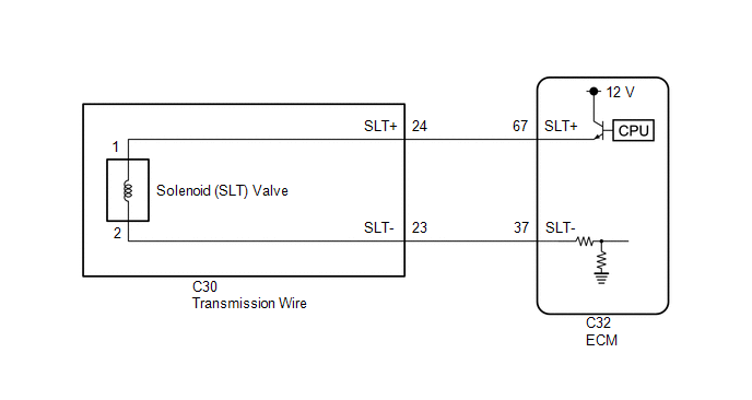
WIRING DIAGRAM
CAUTION / NOTICE / HINT
NOTICE:
-
Perform the universal trip to clear permanent DTCs.
Click here
-
Perform registration and/or initialization when parts related to the automatic transaxle are replaced.
Click here
PROCEDURE
| 1. | CHECK HARNESS AND CONNECTOR (TRANSMISSION WIRE (SOLENOID (SLT) VALVE) - ECM) |
(a) Disconnect the C32 ECM connector.
(b) Measure the resistance according to the value(s) in the table below.
Standard Resistance:
| Tester Connection | Condition | Specified Condition |
|---|---|---|
| C32-67 (SLT+) or C32-37 (SLT-) - Other terminals | Always | 10 kΩ or higher |
| NG | .gif) | GO TO STEP 3 |
|
.gif)
| 2. | REPLACE ECM |
(a) Replace the ECM.
Click here
| NEXT | | PERFORM REGISTRATION |
| 3. | CHECK HARNESS AND CONNECTOR (TRANSMISSION WIRE - ECM) |
(a) Disconnect the C30 transmission wire connector.
(b) Disconnect the C32 ECM connector.
(c) Measure the resistance according to the value(s) in the table below.
Standard Resistance:
| Tester Connection | Condition | Specified Condition |
|---|---|---|
| C30-24 (SLT+) or C32-67 (SLT+) - Other terminals | Always | 10 kΩ or higher |
| C30-23 (SLT-) or C32-37 (SLT-) - Other terminals | Always | 10 kΩ or higher |
| NG | | REPAIR OR REPLACE HARNESS OR CONNECTOR (TRANSMISSION WIRE - ECM) |
|
| 4. | INSPECT SOLENOID (SLT) VALVE |
| (a) Remove the solenoid (SLT) valve. Click here |
|
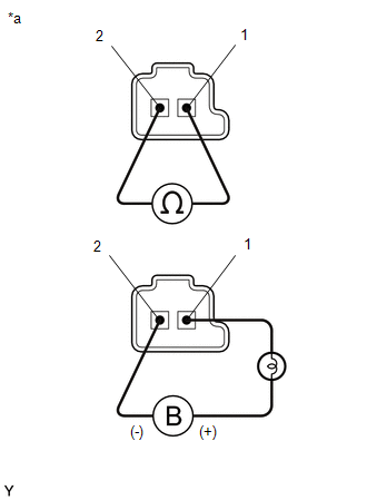
(b) Measure the resistance according to the value(s) in the table below.
Standard Resistance:
| Tester Connection | Condition | Specified Condition |
|---|---|---|
| Solenoid (SLT) valve connector terminal 1 - terminal 2 | 20°C (68°F) | 5.0 to 5.6 Ω |
(c) Connect a positive (+) lead from the battery with a 21 W bulb to terminal 1 and a negative (-) lead to terminal 2 of the solenoid valve connector. Check that the valve moves and makes an operating sound.
OK:
Valve moves and makes an operating sound.
| OK | | REPAIR OR REPLACE TRANSMISSION WIRE |
| NG | | REPLACE SOLENOID (SLT) VALVE |
READ NEXT:
 Pressure Control Solenoid "D" Circuit Short to Ground or Open (P271314)
DESCRIPTION Refer to DTC P27137F. Click here DTC No. Detection Item DTC Detection Condition Trouble Area MIL Memory Note P271314 Pressure Control Solenoid "D" Circuit Short to G
Torque Converter Clutch Pressure Control Solenoid Control Circuit Short to Battery (P275612)
DESCRIPTION The ECM controls the solenoid (SLU) valve using a predetermined current, and performs lock-up and flex lock-up control. *1 Spool Valve *2 Sleeve *3 Solenoid Coil - -
Torque Converter Clutch Pressure Control Solenoid Control Circuit Short to Ground or Open (P275614)
DESCRIPTION Refer to DTC P275612. Click here DTC No. Detection Item DTC Detection Condition Trouble Area MIL Memory Note P275614 Torque Converter Clutch Pressure Control Solenoi
SEE MORE:
Electric Parking Brake System AUTO Function Circuit
DESCRIPTION The skid control ECU (brake actuator assembly) receives shift position signals from the ECM via CAN communication to control the electric parking brake system AUTO function (IG-OFF linked function). The electric parking brake system AUTO function (IG-OFF linked function) is automatically
O2 Sensor Slow Response - Rich to Lean Bank 1 Sensor 1 (P014C00-P014F00,P015A00-P015D00)
DESCRIPTION Refer to DTC P219519. Click here HINT: Although the DTC titles say oxygen sensor, these DTCs relate to the air fuel ratio sensor. DTC No. Detection Item DTC Detection Condition Trouble Area MIL Memory Note P014C00 O2 Sensor Slow Response - Rich to Lean Bank 1 Senso
