Lexus ES: Power Window Motor Malfunction (B2311)
DESCRIPTION
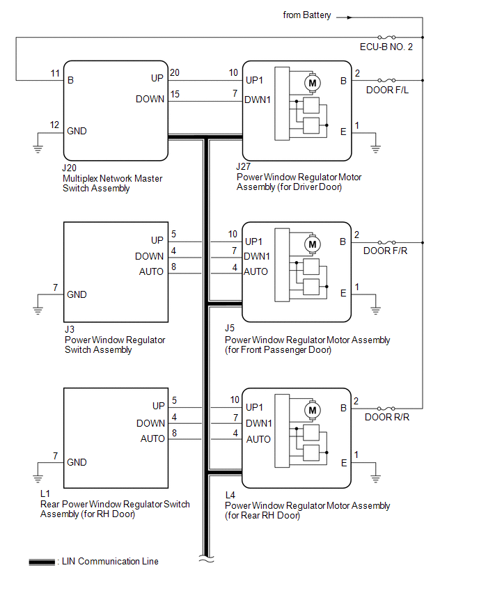
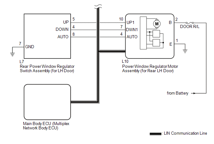
The power window regulator motor assemblies are operated by the multiplex network master switch assembly, power window regulator switch assembly or rear power window regulator switch assemblies. The power window regulator motor assemblies have motor, regulator and ECU functions.
This DTC is stored when a power window regulator motor assembly is malfunctioning, or the ECU built into the power window regulator motor assembly determines that the fully closed power window position has deviated approximately 20 mm (0.787 in.) or more from the normal position.
D-Door Motor| DTC No. | Detection Item | DTC Detection Condition | Trouble Area |
|---|---|---|---|
| B2311 | Power Window Motor Malfunction |
|
|
| DTC No. | Detection Item | DTC Detection Condition | Trouble Area |
|---|---|---|---|
| B2311 | Power Window Motor Malfunction |
|
|
| DTC No. | Detection Item | DTC Detection Condition | Trouble Area |
|---|---|---|---|
| B2311 | Power Window Motor Malfunction |
|
|
| DTC No. | Detection Item | DTC Detection Condition | Trouble Area |
|---|---|---|---|
| B2311 | Power Window Motor Malfunction |
|
|
WIRING DIAGRAM
CAUTION / NOTICE / HINT
NOTICE:
- DTC B2311 is stored in each power window regulator motor assembly.
-
If a power window regulator motor assembly has been replaced with a new one, initialize the power window control system.
Click here
.gif)
-
If a power window regulator motor assembly and door window regulator sub-assembly have been removed and installed, or if a power window regulator motor assembly was reused when a door glass or door glass run was replaced, initialize the power window control system.
Click here
- Inspect the fuses for circuits related to this system before performing the following procedure.
-
The power window control system uses the LIN communication system. Inspect the communication function by following How to Proceed with Troubleshooting. Troubleshoot the power window control system after confirming that the communication system is functioning properly.
Click here
PROCEDURE
| 1. | CHECK FOR DTC |
(a) Connect the Techstream to the DLC3.
(b) Turn the engine switch on (IG).
(c) Turn the Techstream on.
(d) Enter the following menus: Body Electrical / (desired system) / Clear DTCs.
(e) Clear the DTCs.
Body Electrical > D-Door Motor > Clear DTCs Body Electrical > P-Door Motor > Clear DTCs Body Electrical > RL-Door Motor > Clear DTCs Body Electrical > RR-Door Motor > Clear DTCs(f) Check for DTCs.
Body Electrical > D-Door Motor > Trouble Codes Body Electrical > P-Door Motor > Trouble Codes Body Electrical > RL-Door Motor > Trouble Codes Body Electrical > RR-Door Motor > Trouble CodesOK:
DTC B2311 is not output.
| OK | .gif) | USE SIMULATION METHOD TO CHECK |
|
.gif)
| 2. | CHECK DTC OUTPUT |
(a) Check the parts from which this DTC has been output.
| Result | Proceed to |
|---|---|
| DTC output from power window regulator motor assembly (for driver door) | A |
| DTC output from power window regulator motor assembly (for front passenger door) | B |
| DTC output from power window regulator motor assembly (for rear LH door) | C |
| DTC output from power window regulator motor assembly (for rear RH door) | D |
| B | | GO TO STEP 4 |
| C | | GO TO STEP 5 |
| D | | GO TO STEP 6 |
|
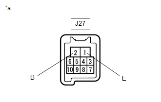
| 3. | CHECK HARNESS AND CONNECTOR (POWER WINDOW REGULATOR MOTOR ASSEMBLY (for Driver Door) - BATTERY AND BODY GROUND) |
| (a) Measure the voltage according to the value(s) in the table below. Standard Voltage:
|
|
(b) Measure the resistance according to the value(s) in the table below.
Standard Resistance:
| Tester Connection | Condition | Specified Condition |
|---|---|---|
| J27-1 (E) - Body ground | Always | Below 1 Ω |
| OK | | GO TO STEP 7 |
| NG | | REPAIR OR REPLACE HARNESS OR CONNECTOR |
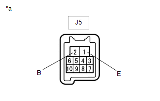
| 4. | CHECK HARNESS AND CONNECTOR (POWER WINDOW REGULATOR MOTOR ASSEMBLY (for Front Passenger Door) - BATTERY AND BODY GROUND) |
| (a) Measure the voltage according to the value(s) in the table below. Standard Voltage:
|
|
(b) Measure the resistance according to the value(s) in the table below.
Standard Resistance:
| Tester Connection | Condition | Specified Condition |
|---|---|---|
| J5-1 (E) - Body ground | Always | Below 1 Ω |
| OK | | GO TO STEP 7 |
| NG | | REPAIR OR REPLACE HARNESS OR CONNECTOR |
| 5. | CHECK HARNESS AND CONNECTOR (POWER WINDOW REGULATOR MOTOR ASSEMBLY (for Rear LH Door) - BATTERY AND BODY GROUND) |
| (a) Measure the voltage according to the value(s) in the table below. Standard Voltage:
|
|
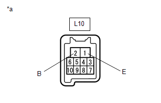
(b) Measure the resistance according to the value(s) in the table below.
Standard Resistance:
| Tester Connection | Condition | Specified Condition |
|---|---|---|
| L10-1 (E) - Body ground | Always | Below 1 Ω |
| OK | | GO TO STEP 7 |
| NG | | REPAIR OR REPLACE HARNESS OR CONNECTOR |
| 6. | CHECK HARNESS AND CONNECTOR (POWER WINDOW REGULATOR MOTOR ASSEMBLY (for Rear RH Door) - BATTERY AND BODY GROUND) |
| (a) Measure the voltage according to the value(s) in the table below. Standard Voltage:
|
|
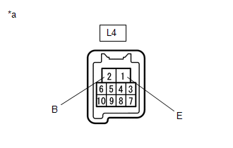
(b) Measure the resistance according to the value(s) in the table below.
Standard Resistance:
| Tester Connection | Condition | Specified Condition |
|---|---|---|
| L4-1 (E) - Body ground | Always | Below 1 Ω |
| NG | | REPAIR OR REPLACE HARNESS OR CONNECTOR |
|
| 7. | PERFORM ACTIVE TEST USING TECHSTREAM (APPLICABLE LOCATION) |
(a) Enter the following menus: Body Electrical / (desired system) / Active Test.
HINT:
Perform the Active Test for the power window regulator motor assembly that has DTC B2311 stored in its ECU.
(b) Perform the Active Test according to the display on the Techstream.
CAUTION:
Be careful to avoid injuries as this test causes vehicle parts to move. During the Active Test, the jam protection function will not operate.
Body Electrical > D-Door Motor > Active Test| Tester Display | Measurement Item | Control Range | Diagnostic Note |
|---|---|---|---|
| Power Window | Power window | OFF / DOWN / UP | - |
| Tester Display | Measurement Item | Control Range | Diagnostic Note |
|---|---|---|---|
| Power Window | Power window | OFF / DOWN / UP | - |
| Tester Display | Measurement Item | Control Range | Diagnostic Note |
|---|---|---|---|
| Power Window | Power window | OFF / DOWN / UP | - |
| Tester Display | Measurement Item | Control Range | Diagnostic Note |
|---|---|---|---|
| Power Window | Power window | OFF / DOWN / UP | - |
| Tester Display |
|---|
| Power Window |
| Tester Display |
|---|
| Power Window |
| Tester Display |
|---|
| Power Window |
| Tester Display |
|---|
| Power Window |
OK:
Each power window operates normally.
| Result | Proceed to |
|---|---|
| OK | A |
| NG (Driver door power window) | B |
| NG (Front passenger door power window) | |
| NG (Rear LH door power window) | C |
| NG (Rear RH door power window) |
| B | | REPLACE POWER WINDOW REGULATOR MOTOR ASSEMBLY (for Driver Door or Front Passenger Door) |
| C | | REPLACE POWER WINDOW REGULATOR MOTOR ASSEMBLY (for Rear LH Door or Rear RH Door) |
|
| 8. | PERFORM INITIALIZATION (APPLICABLE LOCATION) |
(a) Initialize the power window regulator motor assembly.
Click here
HINT:
Initialize the power window regulator motor assembly that has DTC B2311 stored in its ECU.
|
| 9. | CHECK POWER WINDOW CONTROL SYSTEM (APPLICABLE LOCATION) |
(a) Check that the power window operates normally by opening and closing it.
Click here
HINT:
Check the power window operation of the window where DTC B2311 has been stored.
OK:
Each power window operates normally.
| Result | Proceed to |
|---|---|
| OK | A |
| NG (Driver door power window) | B |
| NG (Front passenger door power window) | |
| NG (Rear LH door power window) | C |
| NG (Rear RH door power window) |
| B | | REPLACE POWER WINDOW REGULATOR MOTOR ASSEMBLY (for Driver Door or Front Passenger Door) |
| C | | REPLACE POWER WINDOW REGULATOR MOTOR ASSEMBLY (for Rear LH Door or Rear RH Door) |
|
| 10. | CHECK WHETHER PARTS HAVE BEEN INSTALLED CORRECTLY |
(a) Check that the power window components are installed correctly.
HINT:
Initialize the power window regulator motor assembly that has DTC B2311 stored in its ECU.
OK:
Power window components are installed correctly.
| NG | | INSTALL PARTS CORRECTLY |
|
| 11. | CHECK DTC OUTPUT |
(a) Turn the engine switch off.
(b) Wait for at least 10 seconds, and then turn the engine switch on (IG).
(c) Check for DTCs.
Body Electrical > D-Door Motor > Trouble Codes Body Electrical > P-Door Motor > Trouble Codes Body Electrical > RL-Door Motor > Trouble Codes Body Electrical > RR-Door Motor > Trouble CodesOK:
B2311 is not output.
| Result | Proceed to |
|---|---|
| OK | A |
| NG (Driver door power window) | B |
| NG (Front passenger door power window) | |
| NG (Rear LH door power window) | C |
| NG (Rear RH door power window) |
| A | | END |
| B | | REPLACE POWER WINDOW REGULATOR MOTOR ASSEMBLY (for Driver Door or Front Passenger Door) |
| C | | REPLACE POWER WINDOW REGULATOR MOTOR ASSEMBLY (for Rear LH Door or Rear RH Door) |
READ NEXT:
 Power Window Switch Malfunction (B2312)
DESCRIPTION The power window regulator motor assemblies are operated by the multiplex network master switch assembly, power window regulator switch assembly or rear power window regulator switch assem
Glass Position Initialization Incomplete (B2313)
DESCRIPTION The power window regulator motor assemblies are operated by the multiplex network master switch assembly, power window regulator switch assembly or rear power window regulator switch assem
Remote Up / Down Function does not Operate
DESCRIPTION When the engine switch on (IG), the multiplex network master switch assembly sends remote up and down signals to each power window regulator motor assembly via LIN communication. WIRING DI
SEE MORE:
Fail-safe Chart
FAIL-SAFE CHART PULSE FAILURE (a) If a pulse sensor built into the power window regulator motor assembly malfunctions, the following power window operations will be prohibited. Multiplex Network Master Switch Assembly, Power Window Regulator Switch Assembly, Rear Power Window Regulator Switch Assemb
Components
COMPONENTS ILLUSTRATION *A for Type A *B for Type B *1 FRONT FENDER APRON SEAL LH *2 FRONT FENDER APRON SEAL RH *3 FRONT WHEEL OPENING EXTENSION PAD LH *4 FRONT WHEEL OPENING EXTENSION PAD RH *5 NO. 1 ENGINE UNDER COVER *6 NO. 2 ENGINE UNDER COVER *7 NO.
