Lexus ES: Power Source Circuit
DESCRIPTION
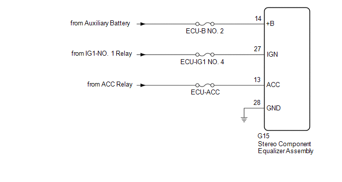
This circuit is the power source circuit for the stereo component equalizer assembly.
WIRING DIAGRAM
CAUTION / NOTICE / HINT
NOTICE:
Inspect the fuses and relays for circuits related to this system before performing the following procedure.
PROCEDURE
| 1. | CHECK HARNESS AND CONNECTOR (STEREO COMPONENT EQUALIZER ASSEMBLY POWER SOURCE) |
| (a) Disconnect the stereo component equalizer assembly connector. |
|
.png)
(b) Measure the voltage according to the value(s) in the table below.
Standard Voltage:
| Tester Connection | Condition | Specified Condition |
|---|---|---|
| G15-14 (+B) - Body ground | Power switch off | 11 to 14 V |
| G15-27 (IGN) - Body ground | Power switch on (IG) | 11 to 14 V |
| G15-13 (ACC) - Body ground | Power switch on (ACC) | 11 to 14 V |
(c) Measure the resistance according to the value(s) in the table below.
Standard Resistance:
| Tester Connection | Condition | Specified Condition |
|---|---|---|
| G15-28 (GND) - Body ground | Always | Below 1 Ω |
| OK | .gif) | PROCEED TO NEXT SUSPECTED AREA SHOWN IN PROBLEM SYMPTOMS TABLE |
| NG | | REPAIR OR REPLACE HARNESS OR CONNECTOR |
READ NEXT:
 Precaution
PRECAUTION PRECAUTION FOR ACTIVE NOISE CONTROL SYSTEM (a) If the active noise control microphone garnish hole is blocked, clean away the blockage and perform diagnosis. (b) If heavy objects are loaded
Problem Symptoms Table
PROBLEM SYMPTOMS TABLE NOTICE:
Before checking parts for malfunctions, check that the audio system operates normally.
Use the table below to help determine the cause of problem symptoms. If multi
System Description
SYSTEM DESCRIPTION ACTIVE NOISE CONTROL SYSTEM (a) The active noise control system is a system that detects muffled engine sounds produced in sync that fluctuates according to the engine speed, by usi
SEE MORE:
Components
COMPONENTS ILLUSTRATION *1 ACCELERATOR PEDAL ASSEMBLY *2 ACCELERATOR PEDAL PAD *3 ACCELERATOR PEDAL SENSOR ASSEMBLY *4 NO. 1 INSTRUMENT PANEL UNDER COVER SUB-ASSEMBLY Tightening torque for "Major areas involving basic vehicle performance such as moving/turning/stopping": N
ECM Communication Circuit (C1203)
DESCRIPTION DTC No. Detection Item INF Code DTC Detection Condition Trouble Area MIL Note C1203 ECM Communication Circuit 1161 Either of the following is detected:
Identification information sent from other ECUs does not match with the value stored when shipped from the f
