Lexus ES: Parts Location
Lexus ES (XZ10) Service Manual / Vehicle Interior / Window / Glass / Windshield Deicer System (for Hv Model) / Parts Location
PARTS LOCATION
ILLUSTRATION
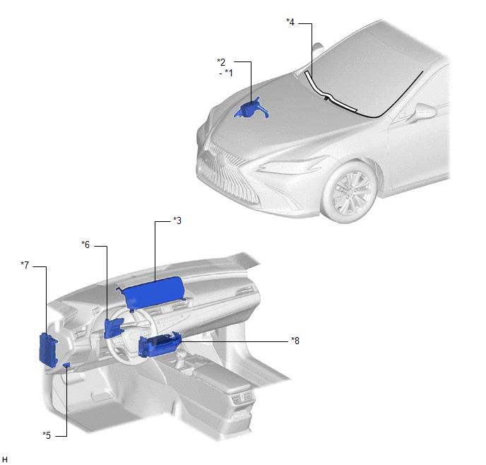
| *1 | DEICER RELAY | *2 | NO. 2 ENGINE ROOM RELAY BLOCK AND NO. 2 ENGINE ROOM JUNCTION BLOCK ASSEMBLY - DEICER FUSE |
| *3 | MULTI-DISPLAY ASSEMBLY - FRONT WIPER DEICER SWITCH | *4 | WINDSHIELD DEICER WIRE (WINDSHIELD GLASS) |
| *5 | DLC3 | *6 | AIR CONDITIONING AMPLIFIER ASSEMBLY |
| *7 | INSTRUMENT PANEL JUNCTION BLOCKASSEMBLY - ECU-IG2 NO. 3 FUSE | *8 | RADIO RECEIVER ASSEMBLY |
READ NEXT:
 System Diagram
SYSTEM DIAGRAM Sender Receiver Signal Communication Method Radio Receiver Assembly Air Conditioning Amplifier Assembly Front wiper deicer switch signal CAN
System Description
SYSTEM DESCRIPTION GENERAL The windshield deicer system uses thin heater wires attached to the inside of the windshield glass to help deice the window surface more quickly. An indicator light illumina
How To Proceed With Troubleshooting
CAUTION / NOTICE / HINT HINT:
Use the following procedure to troubleshoot the windshield deicer system.
*: Use the Techstream.
PROCEDURE 1. VEHICLE BROUGHT TO WORKSHOP
NEXT
SEE MORE:
IGB Signal Circuit Short to Auxiliary Battery (P1CFA12)
DESCRIPTION The hybrid vehicle control ECU monitors the IGB signal received from the certification ECU (smart key ECU assembly). When an error is detected in the IGB signal, this DTC is stored. DTC No. Detection Item DTC Detection Condition Trouble Area MIL Warning Indicate P1CFA12
How To Proceed With Troubleshooting
CAUTION / NOTICE / HINT HINT:
Use the following procedure to troubleshoot the telematics system.
*: Use the Techstream.
PROCEDURE 1. VEHICLE BROUGHT TO WORKSHOP
NEXT 2. CUSTOMER PROBLEM ANALYSIS HINT:
In troubleshooting, check that the problem symptoms h
© 2016-2026 Copyright www.lexguide.net
