Lexus ES: Parts Location
PARTS LOCATION
ILLUSTRATION
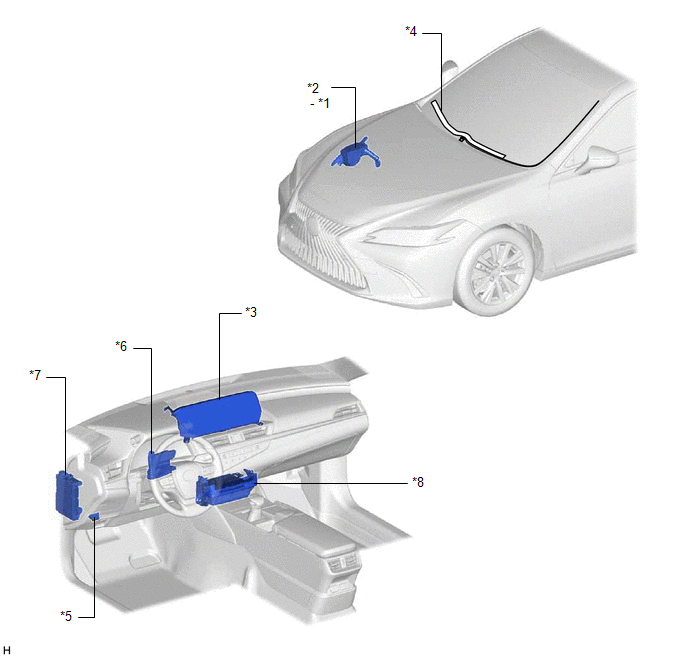
| *1 | DEICER RELAY | *2 | NO. 2 ENGINE ROOM RELAY BLOCK AND NO. 2 ENGINE ROOM JUNCTION BLOCK ASSEMBLY - DEICER FUSE |
| *3 | MULTI-DISPLAY ASSEMBLY - FRONT WIPER DEICER SWITCH | *4 | WINDSHIELD DEICER WIRE (WINDSHIELD GLASS) |
| *5 | DLC3 | *6 | AIR CONDITIONING AMPLIFIER ASSEMBLY |
| *7 | INSTRUMENT PANEL JUNCTION BLOCKASSEMBLY - ECU-IG2 NO. 3 FUSE | *8 | RADIO RECEIVER ASSEMBLY |
READ NEXT:
 System Diagram
SYSTEM DIAGRAM Sender Receiver Signal Communication Method Radio Receiver Assembly Air Conditioning Amplifier Assembly Front wiper deicer switch signal CAN
System Description
SYSTEM DESCRIPTION GENERAL The windshield deicer system uses thin heater wires attached to the inside of the windshield glass to help deice the window surface more quickly. An indicator light illumina
How To Proceed With Troubleshooting
CAUTION / NOTICE / HINT HINT:
Use the following procedure to troubleshoot the windshield deicer system.
*: Use the Techstream.
PROCEDURE 1. VEHICLE BROUGHT TO WORKSHOP
NEXT
SEE MORE:
Operation Check
OPERATION CHECK SELF-DIAGNOSIS SYSTEM (a) When a malfunction occurs in the parking support alert system or the system cannot be used, a warning is displayed on the multi-information display, each indicator blinks or is illuminated, and the meter buzzer sounds to inform the driver that the system is
Throttle Actuator "A" Control System Actuator Stuck Open (P211172,P211173)
DESCRIPTION The throttle actuator is operated by the ECM, and opens and closes the throttle valve using gears. The opening angle of the throttle valve is detected by the throttle position sensor, which is mounted on the throttle body with motor assembly. The throttle position sensor provides feedbac
© 2016-2026 Copyright www.lexguide.net
