Lexus ES: Operation Check
OPERATION CHECK
SELF-DIAGNOSIS SYSTEM
(a) When a malfunction occurs in the parking support alert system or the system cannot be used, a warning is displayed on the multi-information display, each indicator blinks or is illuminated, and the meter buzzer sounds to inform the driver that the system is unavailable.
| Warning Item | Multi-information Display | Indicator/Meter Buzzer Condition |
|---|---|---|
| Static objects function malfunction | Parking Assist Malfunction Visit Your Dealer |
|
| Ultrasonic sensor dirty, frozen or open circuit | Parking Assist Unavailable Clean Parking Assist Sensor |
|
| Parking support alert communication malfunction | Parking Assist Unavailable |
|
| Rear crossing vehicles function malfunction | CHECK RCTA SYSTEM |
|
| Dirt, ice, snow or mud on blind spot monitor sensor | RCTA NOT AVAILABLE |
|
| Rear pedestrians function malfunction | Rear Camera Detection Malfunction Visit Your Dealer |
|
| Rear pedestrians function cannot be used temporarily | Rear Camera Detection Unavailable |
|
| Dirt on television camera assembly | Rear Camera Detection Unavailable Remove the Dirt of Rear Camera |
|
DETECTION RANGE MEASUREMENT AND DISPLAY INSPECTION
NOTICE:
The following measurement and inspection will be performed with the shift lever in a position other than P. Be sure to apply the parking lever and depress the brake pedal firmly to prevent the vehicle from moving.
(a) Turn the engine switch on (IG).
(b) Turn the static objects function is on.
(c) Detection range measurement:
(1) Move the shift lever according to the table below.
| Measurement Area | Shift Lever Position |
| Front Corner Sensor (front corner ultrasonic sensor) | In any position other than P |
| Front Center Sensor (front center ultrasonic sensor) | In any position other than P or R |
| Rear Corner Sensor (rear corner ultrasonic sensor) | R |
| Rear Center Sensor (rear center ultrasonic sensor) |
(2) Move a 60 mm (2.4 in.) diameter pole near each sensor to measure its detection range. When measuring the longest-range detection of a front center sensor or rear center sensor, use a wall or equivalent.
NOTICE:
These detection ranges are applicable when the 60 mm (2.4 in.) diameter pole is positioned parallel or perpendicular to the ground. The detection range varies depending on the measuring method and type of obstacle (such as walls).
HINT:
Have an assistant move the pole.
Front Corner Sensor and Rear Corner Sensor Detection Range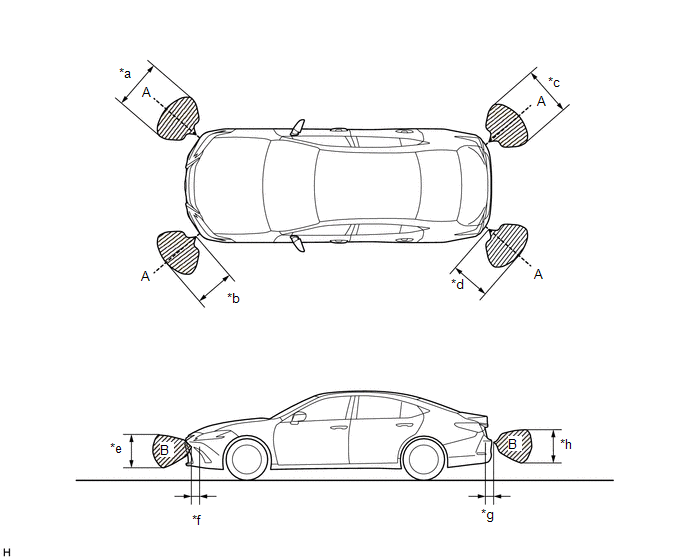
| *a | Approximately 800 mm (31.5 in.) | *b | Approximately 450 mm (17.7 in.) |
| *c | Approximately 860 mm (33.9 in.) | *d | Approximately 500 mm (19.7 in.) |
| *e | Approximately 400 mm (15.7 in.) | *f | Approximately 150 mm (5.91 in.) |
| *g | Approximately 150 mm (5.91 in.) | *h | Approximately 400 mm (15.7 in.) |
NOTICE:
The front corner sensor and rear corner sensor side view detection range (hatched area labeled (B)) represents the cross section of the top view detection range (A). The hatched area (B) does not represent the entire side view detection range.
Front Center Sensor Detection Range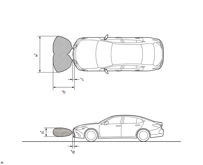
| *a | Approximately 1850 mm (72.8 in.) | *b | Approximately 900 mm (35.4 in.) |
| *c | Approximately 100 mm (3.94 in.) | *d | Approximately 450 mm (17.7 in.) |
| *e | Approximately 100 mm (3.94 in.) | - | - |
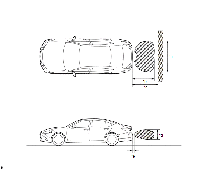
| *a | Approximately 1850 mm (72.8 in.) | *b | Approximately 1100 mm (43.3 in.) |
| *c | Approximately 1500 mm (59.1 in.) | *d | Approximately 450 mm (17.7 in.) |
| *e | Approximately 150 mm (5.91 in.) | - | - |
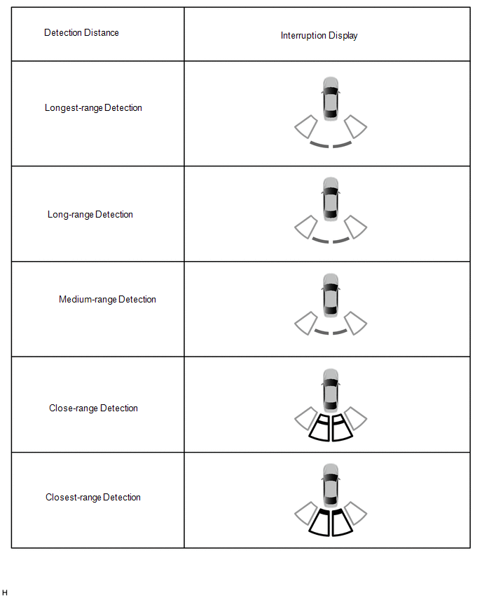
(d) Front corner sensor display and buzzer operation check
(1) When a front corner ultrasonic sensor (front corner sensor) has detected an obstacle, check the displays and that the buzzer sounds.
Operation Condition| Engine States | Static Objects Function | Shift Lever Position | Vehicle Speed* |
|---|---|---|---|
| *: When the shift lever is R, the system operates at any vehicle speed. | |||
| Running | On | In any position other than P |
|
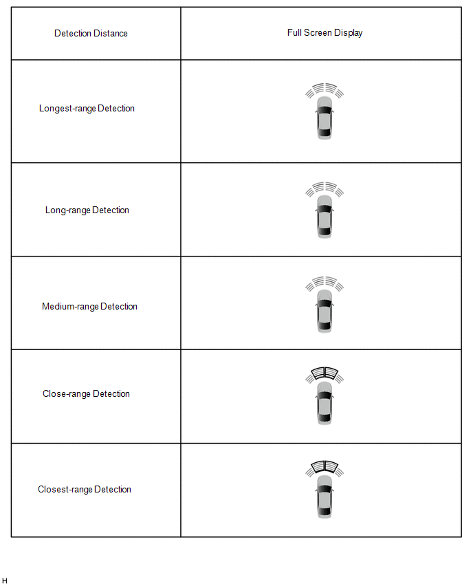
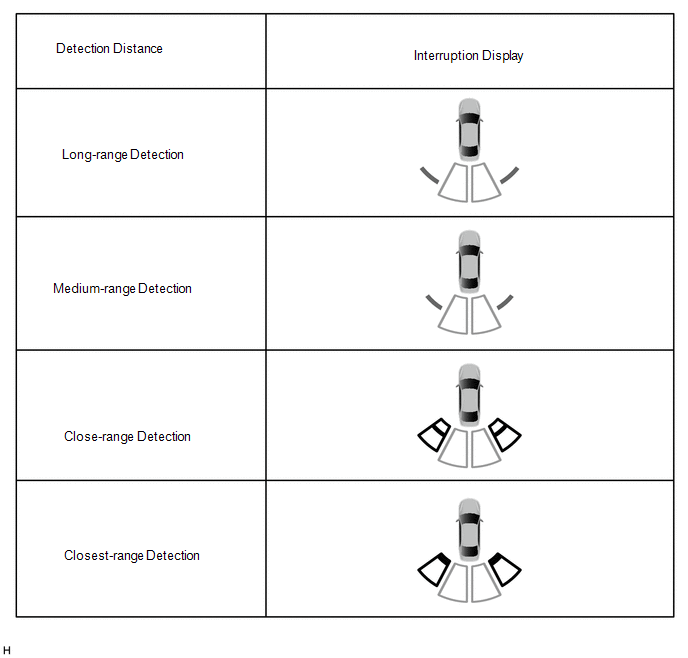
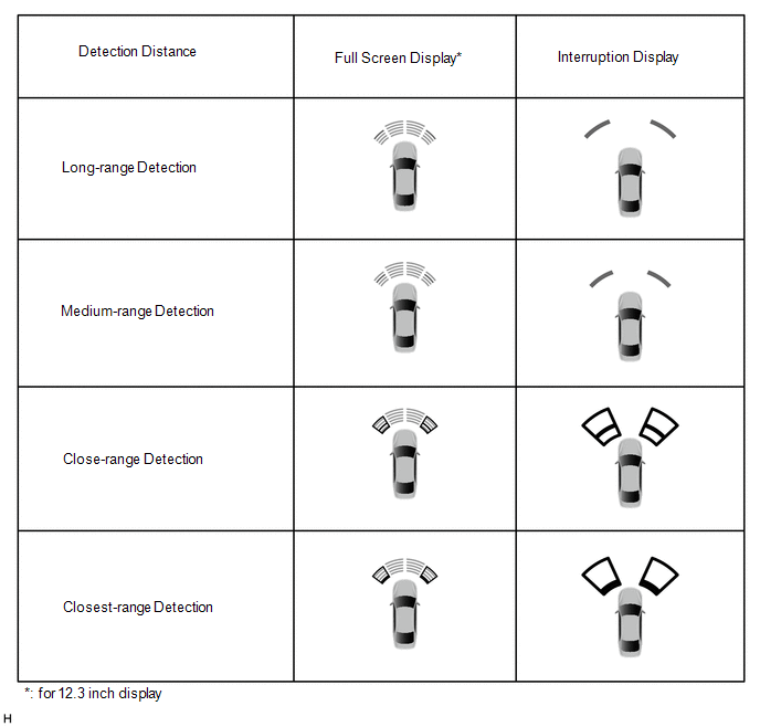 Multi-display Assembly Icon (w/ Panoramic View Monitor System)
 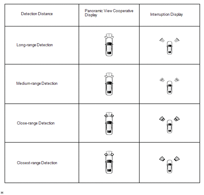 Cornering View and Side Clearance View Icon (for 12.3 inch display w/ Panoramic View Monitor System)
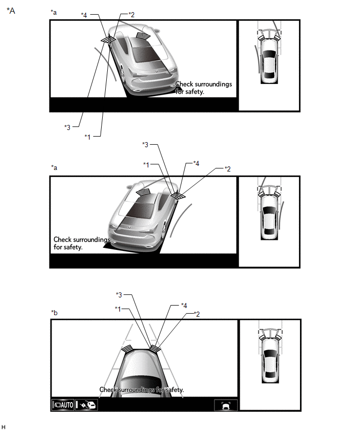
| *A | Example | - | - |
| *a | Panoramic View and Cornering View Display | *b | Panoramic View and Side Clearance View Display |
| *1 | Closest-range | *2 | Close-range |
| *3 | Medium-range | *4 | Long-range |
Standard:
Multi-display, Combination meter assembly, Headup display (w/ Headup Display System) and Buzzer| Detection Range | During Judgment | Obstacle |
|---|---|---|
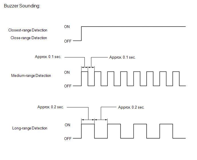
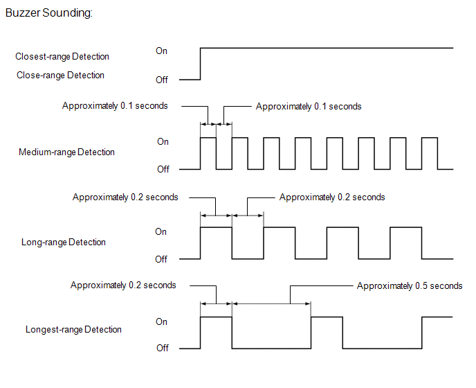
| Closest-range detection Approximately 150 +/- 40 mm (5.91 +/- 1.57 in.) or less | Buzzer: Sounds continuously Color of bars displayed: Red (blinking) | 60 mm (2.4 in.) diameter pole |
| Close-range detection Approximately 300 +/- 40 to 150 +/- 40 mm (11.8 +/-1.57 to 5.91 +/- 1.57 in.) | Buzzer: Sounds continuously Color of bars displayed: Red (blinking) | 60 mm (2.4 in.) diameter pole |
| Medium-range detection Approximately 450 +/- 50 to 300 +/- 40 mm (17.7 +/- 1.97 to 11.8 +/- 1.57 in.) | Buzzer: Sounds intermittently (ON: 0.1 seconds / OFF: 0.1 seconds) Color of bars displayed: Yellow (Illuminated) | 60 mm (2.4 in.) diameter pole |
| Long-range detection Approximately 650 +/- 60 to 450 +/- 50 mm (25.6 +/- 2.36 to 17.7 +/- 1.97 in.) | Buzzer: Sounds intermittently (ON: 0.2 seconds / OFF: 0.2 seconds) Color of bars displayed: Yellow (Illuminated) | 60 mm (2.4 in.) diameter pole |
HINT:
Ultrasonic waves are used to measure the detection range; however, the detection range may vary depending on the ambient temperature.
(e) Front center sensor display and buzzer operation check
(1) When a front center ultrasonic sensor (front center sensor) has detected an obstacle, check the display and that the buzzers sounds.
Operation Condition| Engine States | Static Objects Function | Shift Lever Position | Vehicle Speed |
|---|---|---|---|
| Running | On | In any position other than P or R | Less than approximately 10 km/h (6 mph) if speed is increasing |
 Multi-display Assembly Icon (w/ Panoramic View Monitor System)
 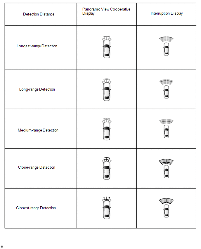 Cornering View and Side Clearance View Icon (for 12.3 inch display w/ Panoramic View Monitor System)
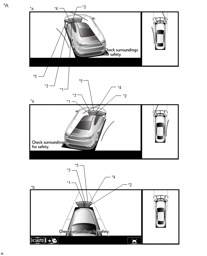
| *A | Example | - | - |
| *a | Panoramic View and Cornering View Display | *b | Panoramic View and Side Clearance View Display |
| *1 | Closest-range | *2 | Close-range |
| *3 | Medium-range | *4 | Long-range |
| *5 | Longest-range | - | - |
Standard:
Multi-display, Combination meter assembly, Headup display (w/ Headup Display System) and Buzzer| Detection Range | During Judgment | Obstacle |
|---|---|---|
| Closest-range detection Approximately 150 +/- 40 mm (5.91 +/- 1.57 in.) or less | Buzzer: Sounds continuously Color of bars displayed: Red (blinking) | 60 mm (2.4 in.) diameter pole |
| Close-range detection Approximately 300 +/- 40 to 150 +/- 40 mm (11.8 +/-1.57 to 5.91 +/- 1.57 in.) | Buzzer: Sounds continuously Color of bars displayed: Red (blinking) | 60 mm (2.4 in.) diameter pole |
| Medium-range detection Approximately 450 +/- 50 to 300 +/- 40 mm (17.7 +/- 1.97 to 11.8 +/- 1.57 in.) | Buzzer: Sounds intermittently (ON: 0.1 seconds / OFF: 0.1 seconds) Color of bars displayed: Yellow (Illuminated) | 60 mm (2.4 in.) diameter pole |
| Long-range detection Approximately 650 +/- 60 to 450 +/- 50 mm (25.6 +/- 2.36 to 17.7 +/- 1.97 in.) | Buzzer: Sounds intermittently (ON: 0.2 seconds / OFF: 0.2 seconds) Color of bars displayed: Yellow (Illuminated) | 60 mm (2.4 in.) diameter pole |
| Longest-range detection Approximately 1000 +/- 110 to 650 +/- 60 mm (39.4 +/- 4.33 to 25.6 +/- 2.36 in.) | Buzzer: Sounds intermittently (ON: 0.2 seconds / OFF: 0.5 seconds) Color of bars displayed: Yellow (Illuminated) | Wall |
HINT:
Ultrasonic waves are used to measure the detection range; however, the detection range may vary depending on the ambient temperature.
(f) Rear corner sensor display and buzzer operation check
(1) When a rear corner ultrasonic sensor (rear corner sensor) has detected an obstacle, check the displays and that the buzzer sounds.
Operation Condition| Engine States | Static Objects Function | Shift Lever Position | Vehicle Speed |
|---|---|---|---|
| Running | On | R | Less than approximately 10 km/h (6 mph) if speed is increasing |
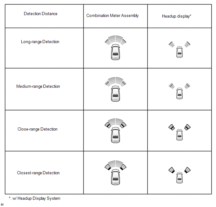
 Multi-display Assembly Icon (w/ Panoramic View Monitor System)
 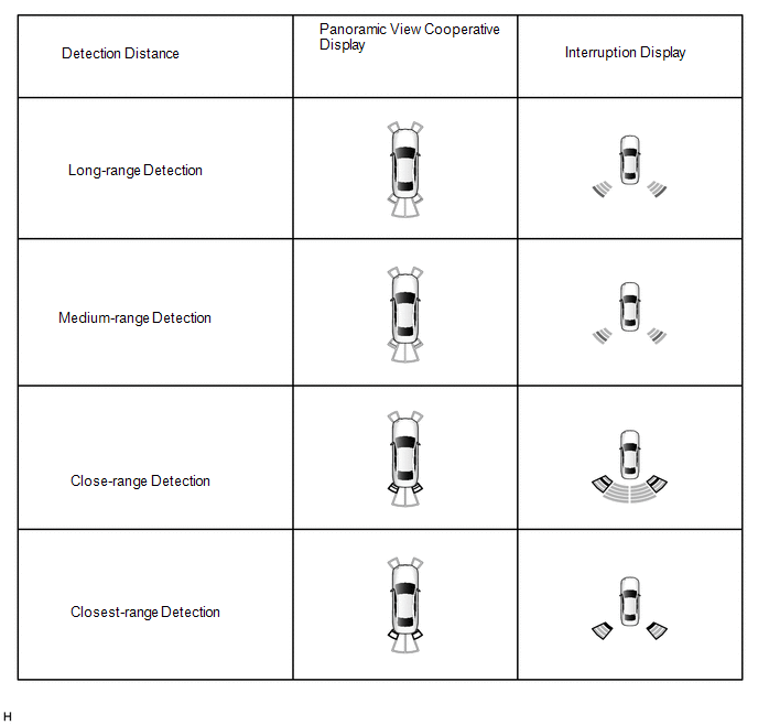 Headup display and Combination Meter Assembly
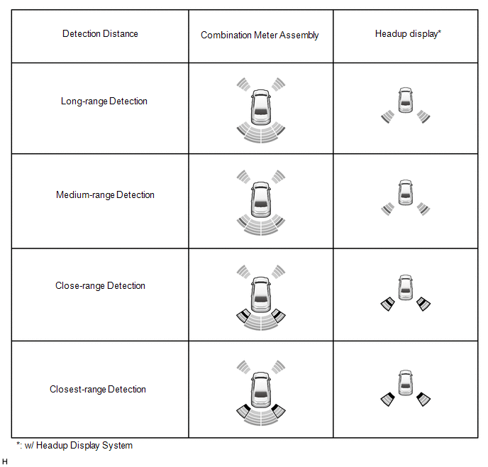
Standard:
Multi-display, Combination meter assembly, Headup display (w/ Headup Display System) and Buzzer| Detection Range | During Judgment | Obstacle |
|---|---|---|
| Closest-range detection Approximately 150 +/- 40 mm (5.91 +/- 1.57 in.) or less | Buzzer: Sounds continuously Color of bars displayed: Red (blinking) | 60 mm (2.4 in.) diameter pole |
| Close-range detection Approximately 300 +/- 40 to 150 +/- 40 mm (11.8 +/-1.57 to 5.91 +/- 1.57 in.) | Buzzer: Sounds continuously Color of bars displayed: Red (blinking) | 60 mm (2.4 in.) diameter pole |
| Medium-range detection Approximately 450 +/- 50 to 300 +/- 40 mm (17.7 +/- 1.97 to 11.8 +/- 1.57 in.) | Buzzer: Sounds intermittently (ON: 0.1 seconds / OFF: 0.1 seconds) Color of bars displayed: Yellow (Illuminated) | 60 mm (2.4 in.) diameter pole |
| Long-range detection Approximately 650 +/- 60 to 450 +/- 50 mm (25.6 +/- 2.36 to 17.7 +/- 1.97 in.) | Buzzer: Sounds intermittently (ON: 0.2 seconds / OFF: 0.2 seconds) Color of bars displayed: Yellow (Illuminated) | 60 mm (2.4 in.) diameter pole |
HINT:
Ultrasonic waves are used to measure the detection range; however, the detection range may vary depending on the ambient temperature.
(g) Rear center sensor display and buzzer operation check
(1) When a rear center ultrasonic sensor (rear center sensor) has detected an obstacle, the displays and that the buzzer sounds.
Operation Condition| Engine States | Static Objects Function | Shift Lever Position | Vehicle Speed |
|---|---|---|---|
| Running | On | R | Less than approximately 10 km/h (6 mph) if speed is increasing |
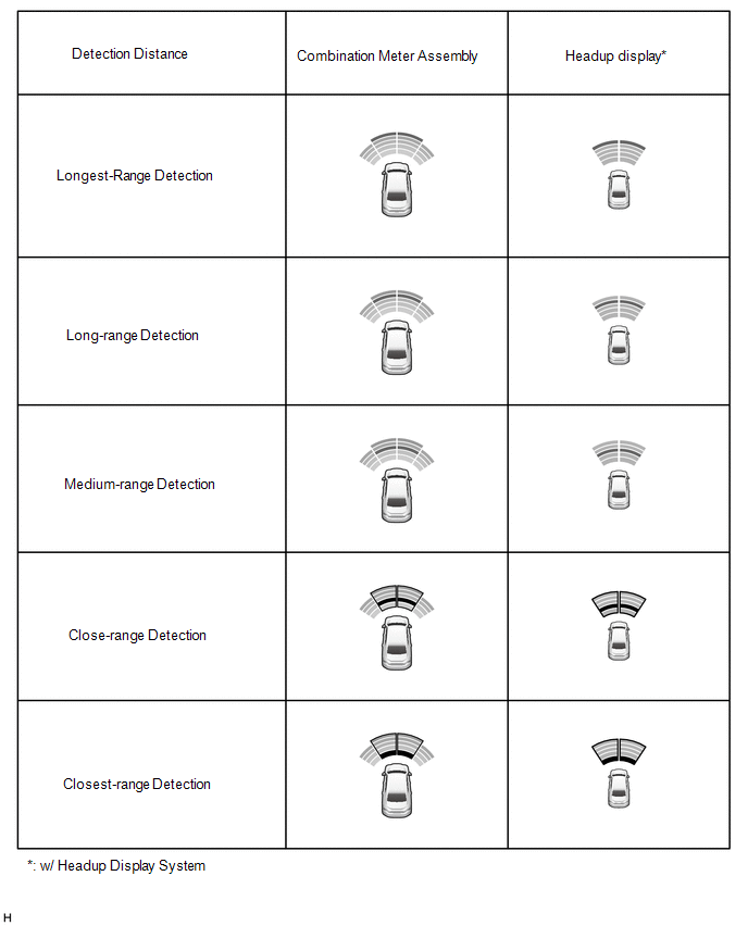
 Multi-display Assembly Icon (w/ Panoramic View Monitor System)
 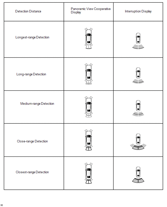 Headup display and Combination Meter Assembly
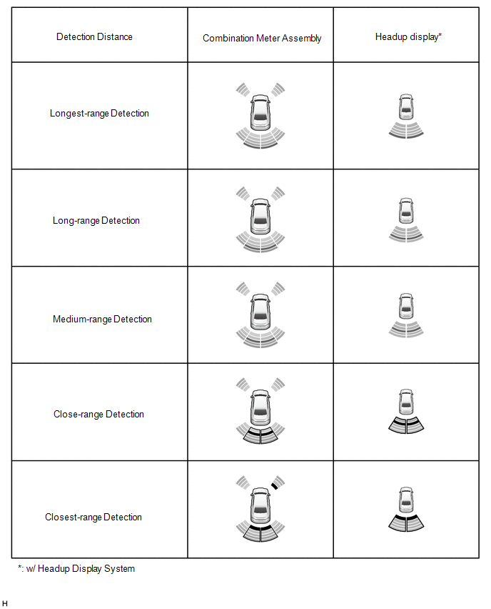
Standard:
Multi-display, Combination meter assembly, Headup display (w/ Headup Display System) and Buzzer| Detection Range | During Judgment | Obstacle |
|---|---|---|
| Closest-range detection Approximately 150 +/- 40 mm (5.91 +/- 1.57 in.) or less | Buzzer: Sounds continuously Color of bars displayed: Red (blinking) | 60 mm (2.4 in.) diameter pole |
| Close-range detection Approximately 300 +/- 40 to 150 +/- 40 mm (11.8 +/-1.57 to 5.91 +/- 1.57 in.) | Buzzer: Sounds continuously Color of bars displayed: Red (blinking) | 60 mm (2.4 in.) diameter pole |
| Medium-range detection Approximately 450 +/- 50 to 300 +/- 40 mm (17.7 +/- 1.97 to 11.8 +/- 1.57 in.) | Buzzer: Sounds intermittently (ON: 0.1 seconds / OFF: 0.1 seconds) Color of bars displayed: Yellow (Illuminated) | 60 mm (2.4 in.) diameter pole |
| Long-range detection Approximately 650 +/- 60 to 450 +/- 50 mm (25.6 +/- 2.36 to 17.7 +/- 1.97 in.) | Buzzer: Sounds intermittently (ON: 0.2 seconds / OFF: 0.2 seconds) Color of bars displayed: Yellow (Illuminated) | 60 mm (2.4 in.) diameter pole |
| Longest-range detection Approximately 1500 +/- 110 to 650 +/- 60 mm (59.1 +/- 4.33 to 25.6 +/- 2.36 in.) | Buzzer: Sounds intermittently (ON: 0.2 seconds / OFF: 0.5 seconds) Color of bars displayed: Yellow (Illuminated) | Wall |
HINT:
Ultrasonic waves are used to measure the detection range; however, the detection range may vary depending on the ambient temperature.
READ NEXT:
 Parts Location
PARTS LOCATION ILLUSTRATION *1 FRONT CORNER ULTRASONIC SENSOR RH *2 FRONT CENTER ULTRASONIC SENSOR RH *3 FRONT CENTER ULTRASONIC SENSOR LH *4 FRONT CORNER ULTRASONIC SENSOR LH
Precaution
PRECAUTION PRECAUTION FOR DISCONNECTING CABLE FROM NEGATIVE BATTERY TERMINAL NOTICE: When disconnecting the cable from the negative (-) battery terminal, initialize the following systems after the cab
Problem Symptoms Table
PROBLEM SYMPTOMS TABLE HINT:
Use the table below to help determine the cause of problem symptoms. If multiple suspected areas are listed, the potential causes of the symptoms are listed in order of
SEE MORE:
Evaporative Emission Canister (Small Leak) (P142000,P142100)
DTC SUMMARY DTC No. Detection Item DTC Detection Condition Trouble Area MIL Memory Note P142000 Evaporative Emission Canister (Small Leak) Leak detection pump creates negative pressure (vacuum) in EVAP system and EVAP system pressure is measured. Reference pressure is measured
Parking Support Brake function
(static objects)
If the sensors detect a static object, such as a wall, in the traveling
direction of
the vehicle and the system determines that a collision may occur due to the
vehicle suddenly moving forward due to an accidental accelerator pedal
operation,
the vehicle moving the unintended direction due to
