Lexus ES: Parts Location
PARTS LOCATION
ILLUSTRATION
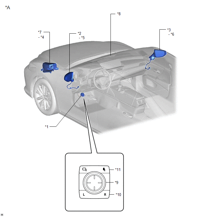
| *1 | OUTER MIRROR SWITCH ASSEMBLY | *2 | OUTER REAR VIEW MIRROR ASSEMBLY LH |
| *3 | OUTER REAR VIEW MIRROR ASSEMBLY RH | *4 | DEF RELAY |
| *5 | OUTER MIRROR LH | *6 | OUTER MIRROR RH |
| *7 | NO. 1 ENGINE ROOM RELAY BLOCK AND NO. 1 JUNCTION BLOCK ASSEMBLY - DEF FUSE - MIR HTR FUSE | *8 | INNER REAR VIEW MIRROR ASSEMBLY |
| *9 | MIRROR ADJUST SWITCH | *10 | MIRROR SELECT SWITCH |
ILLUSTRATION
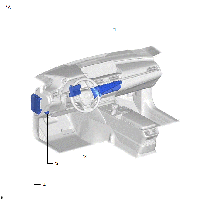
| *1 | REAR WINDOW DEFOGGER SWITCH (AIR CONDITIONING CONTROL ASSEMBLY) | *2 | DLC3 |
| *3 | AIR CONDITIONING AMPLIFIER ASSEMBLY | *4 | INSTRUMENT PANEL JUNCTION BLOCK ASSEMBLY - ECU-ACC FUSE - ECU-IG1 NO. 3 FUSE |
READ NEXT:
 System Diagram
SYSTEM DIAGRAM ELECTRICAL REMOTE CONTROL MIRROR FUNCTION MIRROR HEATER FUNCTION AUTOMATIC GLARE-RESISTANT EC MIRROR FUNCTION Communication Table Sender Receiver Signal Communication Metho
System Description
SYSTEM DESCRIPTION POWER MIRROR CONTROL SYSTEM (w/o Memory) DESCRIPTION (a) This system has the following functions: electrical remote control mirror function, power retract mirror function, mirror he
How To Proceed With Troubleshooting
CAUTION / NOTICE / HINT HINT:
Use the following procedure to troubleshoot the power mirror control system (w/o Memory).
*: Use the Techstream.
PROCEDURE 1. VEHICLE BROUGHT TO WORKSHOP
SEE MORE:
Wiper Motor Power Source Circuit
DESCRIPTION This circuit is the power source circuit for the windshield wiper motor assembly. WIRING DIAGRAM CAUTION / NOTICE / HINT NOTICE:
Inspect the fuses of circuits related to this system before performing the following procedure.
Before replacing the main body ECU (multiplex network bod
Stereo Component Amplifier Malfunction (B15A3)
DESCRIPTION This DTC is stored when a malfunction occurs in the stereo component amplifier assembly. DTC No. Detection Item DTC Detection Condition Trouble Area B15A3 Stereo Component Amplifier Malfunction When any of the following conditions is met:
Internal power supply malfunc
© 2016-2026 Copyright www.lexguide.net
