Lexus ES: Parts Location
PARTS LOCATION
ILLUSTRATION
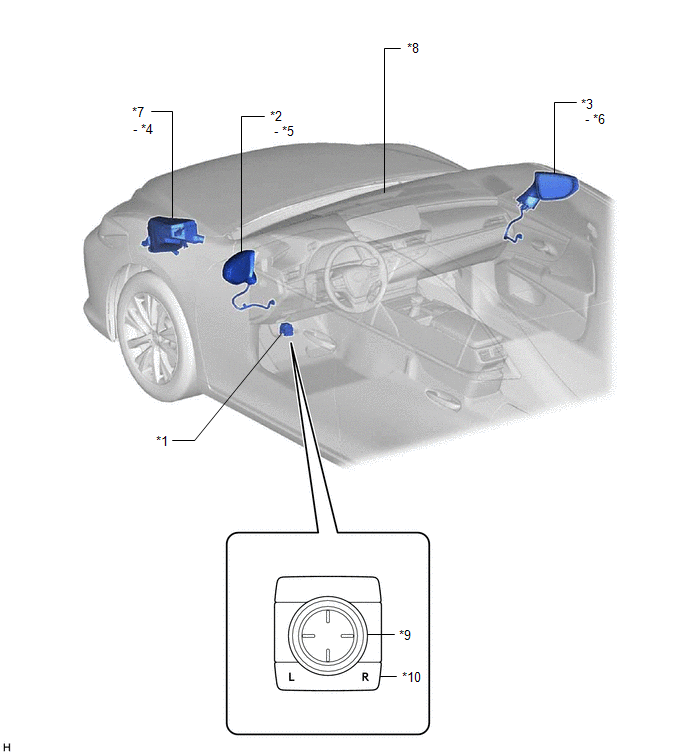
| *1 | OUTER MIRROR SWITCH ASSEMBLY | *2 | OUTER REAR VIEW MIRROR ASSEMBLY LH |
| *3 | OUTER REAR VIEW MIRROR ASSEMBLY RH | *4 | DEF RELAY |
| *5 | OUTER MIRROR LH | *6 | OUTER MIRROR RH |
| *7 | NO. 1 ENGINE ROOM RELAY BLOCK AND NO. 1 JUNCTION BLOCK ASSEMBLY - DEF FUSE - MIR HTR FUSE | *8 | INNER REAR VIEW MIRROR ASSEMBLY |
| *9 | MIRROR ADJUST SWITCH | *10 | MIRROR SELECT SWITCH |
ILLUSTRATION
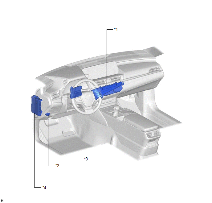
| *1 | REAR WINDOW DEFOGGER SWITCH (AIR CONDITIONING CONTROL ASSEMBLY) | *2 | DLC3 |
| *3 | AIR CONDITIONING AMPLIFIER ASSEMBLY | *4 | INSTRUMENT PANEL JUNCTION BLOCK ASSEMBLY - ECU-ACC FUSE - ECU-IG1 NO. 3 FUSE |
READ NEXT:
 System Diagram
SYSTEM DIAGRAM ELECTRICAL REMOTE CONTROL MIRROR FUNCTION MIRROR HEATER FUNCTION AUTOMATIC GLARE-RESISTANT EC MIRROR FUNCTION Communication Table Sender Receiver Signal Communication Metho
System Description
SYSTEM DESCRIPTION POWER MIRROR CONTROL SYSTEM (w/o Memory) DESCRIPTION (a) This system has the following functions: electrical remote control mirror function, power retract mirror function, mirror he
How To Proceed With Troubleshooting
CAUTION / NOTICE / HINT HINT:
Use the following procedure to troubleshoot the power mirror control system (w/o Memory).
*: Use the Techstream.
PROCEDURE 1. VEHICLE BROUGHT TO WORKSHOP
SEE MORE:
System Diagram
SYSTEM DIAGRAM Communication Table Transmitting ECU Receiving ECU Signal Communication Method Certification ECU (smart key ECU assembly) Main body ECU (multiplex network body ECU) Luggage electrical key switch signal CAN Combination meter assembly Main body ECU (multiplex
Screen Flicker or Color Distortion
PROCEDURE 1. CHECK DISPLAY SETTING (a) Reset display settings (contrast, brightness) and check that the screen appears normal. OK: The display returns to normal. OK END (DISPLAY SETTING WAS CAUSE OF MALFUNCTION) NG PROCEED TO NEXT SUSPECTED AREA SHOWN IN PROBLEM SYMPTOMS TA
© 2016-2026 Copyright www.lexguide.net
