Lexus ES: Mirror Heater does not Operate with Rear Defogger Switch
DESCRIPTION
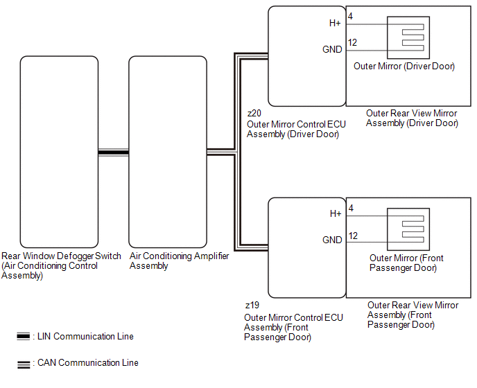
When the mirror heater switch (rear window defogger switch) is operated, the mirror heater signal is sent to the air conditioning amplifier assembly and then to each outer mirror control ECU assembly via CAN communication. Based on this signal, the outer mirror control ECU assemblies operate the mirror heaters.
WIRING DIAGRAM
CAUTION / NOTICE / HINT
NOTICE:
-
The power mirror control system (w/ Memory) uses the CAN communication system. Inspect the communication functions by following How to Proceed with Troubleshooting. Troubleshoot the power mirror control system (w/ Memory) after confirming that the communication systems are functioning properly.
Click here
.gif)
- If the auxiliary battery voltage is low, auxiliary battery load control will operate in order to ensure sufficient power is supplied to the power steering system. In this case, the mirror heater function may not operate.
PROCEDURE
| 1. | CHECK WINDOW DEFOGGER SYSTEM |
(a) Check window defogger system operation.
Click here
OK:
Window defogger system is normal.
| NG | .gif) | GO TO WINDOW DEFOGGER SYSTEM |
|
.gif)
| 2. | PERFORM ACTIVE TEST USING TECHSTREAM |
(a) Connect the Techstream to the DLC3.
(b) Turn the power switch on (IG).
(c) Turn the Techstream on.
(d) Enter the following menus: Body Electrical / Mirror L or Mirror R / Active Test.
(e) Perform an Active Test according to the display on the Techstream.
Body Electrical > Mirror L > Active Test| Tester Display | Measurement Item | Control Range | Diagnostic Note |
|---|---|---|---|
| Mirror Heater | Mirror heater operation | OFF or ON |
|
| Tester Display |
|---|
| Mirror Heater |
| Tester Display | Measurement Item | Control Range | Diagnostic Note |
|---|---|---|---|
| Mirror Heater | Mirror heater operation | OFF or ON |
|
| Tester Display |
|---|
| Mirror Heater |
| Result | Proceed to |
|---|---|
| Mirror heater operation on both mirrors is normal | A |
| Mirror heater operation on driver door mirror is not normal | B |
| Mirror heater operation on front passenger door mirror is not normal | C |
| A | | REPLACE AIR CONDITIONING AMPLIFIER ASSEMBLY |
| C | | GO TO STEP 5 |
|
| 3. | INSPECT OUTER REAR VIEW MIRROR ASSEMBLY (DRIVER DOOR) (MIRROR HEATER) |
(a) Remove the outer rear view mirror assembly (driver door).
Click here
(b) Remove the outer rear view mirror assembly (driver door) (mirror heater).
Click here
| OK | | REPLACE OUTER MIRROR CONTROL ECU ASSEMBLY (DRIVER DOOR) |
|
| 4. | INSPECT OUTER MIRROR (DRIVER DOOR) |
(a) Remove the outer mirror (driver door).
Click here
(b) Inspect the outer mirror (driver door).
Click here
| OK | | REPLACE OUTER REAR VIEW MIRROR ASSEMBLY (DRIVER DOOR) |
| NG | | REPLACE OUTER MIRROR (DRIVER DOOR) |
| 5. | INSPECT OUTER REAR VIEW MIRROR ASSEMBLY (FRONT PASSENGER DOOR) (MIRROR HEATER) |
(a) Remove the outer rear view mirror assembly (front passenger door).
Click here
(b) Remove the outer rear view mirror assembly (front passenger door) (mirror heater).
Click here
| OK | | REPLACE OUTER MIRROR CONTROL ECU ASSEMBLY (FRONT PASSENGER DOOR) |
|
| 6. | INSPECT OUTER MIRROR (FRONT PASSENGER DOOR) |
(a) Remove the outer mirror (front passenger door).
Click here
(b) Inspect the outer mirror (front passenger door).
Click here
| OK | | REPLACE OUTER REAR VIEW MIRROR ASSEMBLY (FRONT PASSENGER DOOR) |
| NG | | REPLACE OUTER MIRROR (FRONT PASSENGER DOOR) |
READ NEXT:
 Power Retractable Mirrors do not Operate with Power Retract Mirror Switch
DESCRIPTION The outer mirror switch assembly sends the retractable outer mirror switch signal to the main body ECU (multiplex network body ECU). The main body ECU (multiplex network body ECU) then sen
AUTO Power Retract Mirrors do not operate
DESCRIPTION The outer mirror switch assembly sends the retractable outer mirror switch signal to the main body ECU (multiplex network body ECU). The main body ECU (multiplex network body ECU) sends th
Power Mirror Surface Position is not Memorized
DESCRIPTION If any of the M1, M2 or M3 seat memory switch is pressed, the outer mirror control ECU assembly (driver door) detects the switch operation and sends the seat memory switch signal to the ma
SEE MORE:
Brake System Control Module "A" System Internal Failure (C059704)
DESCRIPTION The skid control ECU (brake actuator assembly) stores this DTC if malfunctions are found in a circuit inside the ECU by self diagnosis. DTC No. Detection Item DTC Detection Condition Trouble Area C059704 Brake System Control Module "A" System Internal Failure Internal fa
Terminals Of Ecu
TERMINALS OF ECU HINT: Check from the rear of the connector while it is connected to the components. RADIO RECEIVER ASSEMBLY Terminal No. (Symbol) Wiring Color Terminal Description Condition Specified Condition
*1: w/ Manual (SOS) Switch
*2: It is connected, but not used *3: w/o Manu
