Lexus ES: Luggage Compartment Door Opener does not Operate
DESCRIPTION
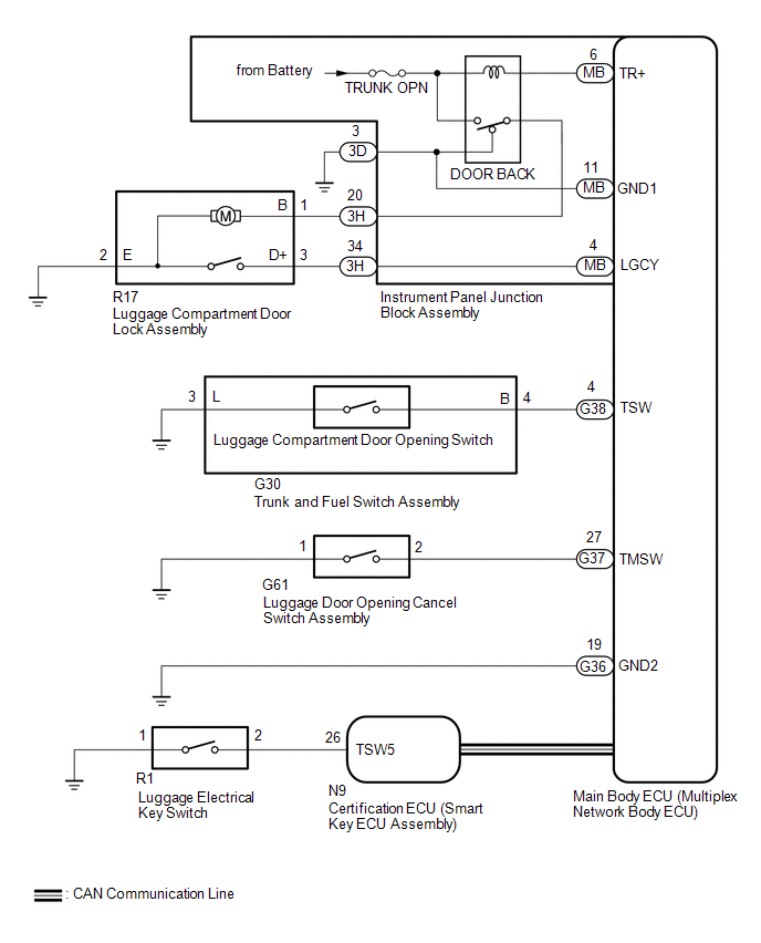
The main body ECU (multiplex network body ECU) receives switch signals from the trunk and fuel switch assembly (luggage compartment door opening switch) the luggage door opening cancel switch, and operates the luggage compartment door lock assembly to open the luggage compartment door.
WIRING DIAGRAM
CAUTION / NOTICE / HINT
NOTICE:
-
The luggage compartment door opener system uses the CAN communication system. First, confirm that there is no malfunction in the CAN communication system. Refer to the How to Proceed with Troubleshooting procedure.
Click here
.gif)
-
Before replacing the main body ECU (multiplex network body ECU) or certification ECU (smart key ECU assembly), refer to Registration.
Click here
- Inspect the fuses for circuits related to this system before performing the following procedure.
PROCEDURE
| 1. | CHECK POWER DOOR LOCK CONTROL SYSTEM |
(a) Check power door lock control system operation.
Click here
OK:
Power door lock control system is normal.
| NG | .gif) | GO TO POWER DOOR LOCK CONTROL SYSTEM |
|
.gif)
| 2. | CHECK WIRELESS DOOR LOCK CONTROL SYSTEM |
(a) Check wireless door lock control system operation.
Click here
OK:
Wireless door lock control system is normal.
| NG | | GO TO WIRELESS DOOR LOCK CONTROL SYSTEM |
|
| 3. | PERFORM ACTIVE TEST USING TECHSTREAM (TRUNK AND BACK-DOOR OPEN) |
(a) Connect the Techstream to the DLC3.
(b) Turn the engine switch on (IG).
(c) Turn the Techstream on.
(d) Enter the following menus: Body Electrical / Main Body / Active Test.
(e) Perform the Active Test according to the display on the Techstream.
Body Electrical > Main Body > Active Test| Tester Display | Measurement Item | Control Range | Diagnostic Note |
|---|---|---|---|
| Trunk and Back-Door Open | Operate luggage compartment door lock assembly latch release | OFF or ON | - |
| Tester Display |
|---|
| Trunk and Back-Door Open |
OK:
Luggage compartment door lock assembly latch release motor operates normally.
| NG | | GO TO STEP 10 |
|
| 4. | READ VALUE USING TECHSTREAM (TRUNK/BDOOR OPEN SW, TRUNK MAIN SW, LUGGAGE COURTESY SW) |
(a) Enter the following menus: Body Electrical / Main Body / Data List.
(b) Read the Data List according to the display on the Techstream.
Body Electrical > Main Body > Data List| Tester Display | Measurement Item | Range | Normal Condition | Diagnostic Note |
|---|---|---|---|---|
| Trunk/BDoor Open SW | Luggage compartment door opening switch signal | OFF or ON | OFF: Luggage compartment door opening switch off ON: Luggage compartment door opening switch on | - |
| Trunk Main SW | Luggage door opening cancel switch signal | OFF or ON | OFF: Luggage door opening cancel switch off ON: Luggage door opening cancel switch on | - |
| Luggage Courtesy SW | Luggage compartment door courtesy light switch signal | OFF or ON | OFF: Luggage compartment door courtesy light switch off ON: Luggage compartment door courtesy light switch on | - |
| Tester Display |
|---|
| Trunk/BDoor Open SW |
| Trunk Main SW |
| Luggage Courtesy SW |
OK:
The Techstream display changes correctly in response to the ON/OFF operation of the luggage compartment door opening switch or luggage compartment door courtesy light switch.
| Result | Proceed to |
|---|---|
| OK | A |
| NG (Trunk/BDoor Open SW) | B |
| NG (Trunk Main SW) | C |
| NG (Luggage Courtesy SW) | D |
| B | | GO TO STEP 6 |
| C | | GO TO STEP 8 |
| D | | GO TO LIGHTING SYSTEM |
|
| 5. | READ VALUE USING TECHSTREAM (TR/B-DOOR UNLOCK SW) |
(a) Enter the following menus: Body Electrical / Smart Access / Data List.
(b) Read the Data List according to the display on the Techstream.
Body Electrical > Smart Access > Data List| Tester Display | Measurement Item | Range | Normal Condition | Diagnostic Note |
|---|---|---|---|---|
| Tr/B-Door Unlock SW | Luggage electrical key switch | OFF or ON | OFF: Luggage electrical key switch not pressed ON: Luggage electrical key switch pressed | When this item is abnormal, there is a malfunction in the luggage electrical key switch or related parts. |
OK:
The Techstream display changes correctly in response to the operation of the luggage electrical key switch.
| OK | | REPLACE MAIN BODY ECU (MULTIPLEX NETWORK BODY ECU) |
| NG | | GO TO SMART ACCESS SYSTEM (for Entry Function) |
| 6. | INSPECT TRUNK AND FUEL SWITCH ASSEMBLY (LUGGAGE COMPARTMENT DOOR OPENING SWITCH) |
(a) Remove the trunk and fuel switch assembly (luggage compartment door opening switch).
Click here
(b) Inspect the trunk and fuel switch assembly (luggage compartment door opening switch).
Click here
| NG | | REPLACE TRUNK AND FUEL SWITCH ASSEMBLY (LUGGAGE COMPARTMENT DOOR OPENING SWITCH) |
|
| 7. | CHECK HARNESS AND CONNECTOR (MAIN BODY ECU (MULTIPLEX NETWORK BODY ECU) - TRUNK AND FUEL SWITCH ASSEMBLY AND BODY GROUND) |
(a) Disconnect the G38 main body ECU (multiplex network body ECU) connector.
(b) Measure the resistance according to the value(s) in the table below.
Standard Resistance:
| Tester Connection | Condition | Specified Condition |
|---|---|---|
| G38-4 (TSW) - G30-4 (B) | Always | Below 1 Ω |
| G30-3 (L) - Body ground | Always | Below 1 Ω |
| G38-4 (TSW) or G30-4 (B) - Body ground | Always | 10 kΩ or higher |
| OK | | REPLACE MAIN BODY ECU (MULTIPLEX NETWORK BODY ECU) |
| NG | | REPAIR OR REPLACE HARNESS OR CONNECTOR |
| 8. | INSPECT TRUNK AND FUEL SWITCH ASSEMBLY (LUGGAGE COMPARTMENT DOOR OPENING SWITCH) |
(a) Remove the trunk and fuel switch assembly (luggage compartment door opening switch).
Click here
(b) Inspect the trunk and fuel switch assembly (luggage compartment door opening switch).
Click here
| NG | | REPLACE TRUNK AND FUEL SWITCH ASSEMBLY (LUGGAGE COMPARTMENT DOOR OPENING SWITCH) |
|
| 9. | CHECK HARNESS AND CONNECTOR (MAIN BODY ECU (MULTIPLEX NETWORK BODY ECU) - LUGGAGE DOOR OPENING CANCEL SWITCH ASSEMBLY AND BODY GROUND) |
(a) Disconnect the G37 main body ECU (multiplex network body ECU) connector.
(b) Measure the resistance according to the value(s) in the table below.
Standard Resistance:
| Tester Connection | Condition | Specified Condition |
|---|---|---|
| G37-27 (TMSW) - G61-2 (B) | Always | Below 1 Ω |
| G61-1 (L) - Body ground | Always | Below 1 Ω |
| G37-27 (TMSW) or G61-2 (B) - Body ground | Always | 10 kΩ or higher |
| OK | | REPLACE MAIN BODY ECU (MULTIPLEX NETWORK BODY ECU) |
| NG | | REPAIR OR REPLACE HARNESS OR CONNECTOR |
| 10. | INSPECT LUGGAGE COMPARTMENT DOOR LOCK ASSEMBLY |
(a) Remove the luggage compartment door lock assembly.
Click here
(b) Inspect the luggage compartment door lock assembly.
Click here
| NG | | REPLACE LUGGAGE COMPARTMENT DOOR LOCK ASSEMBLY |
|
| 11. | CHECK HARNESS AND CONNECTOR (LUGGAGE COMPARTMENT DOOR LOCK ASSEMBLY - INSTRUMENT PANEL JUNCTION BLOCK ASSEMBLY AND BODY GROUND) |
(a) Disconnect the 3H instrument panel junction block assembly connector.
(b) Measure the resistance according to the value(s) in the table below.
Standard Resistance:
| Tester Connection | Condition | Specified Condition |
|---|---|---|
| R17-3 (D+) - 3H-34 | Always | Below 1 Ω |
| R17-1 (B) - 3H-20 | Always | Below 1 Ω |
| R17-2 (E) - Body ground | Always | Below 1 Ω |
| R17-3 (D+) or 3H-34 - Body ground | Always | 10 kΩ or higher |
| R17-1 (B) or 3H-20 - Body ground | Always | 10 kΩ or higher |
| NG | | REPAIR OR REPLACE HARNESS OR CONNECTOR |
|
| 12. | CHECK INSTRUMENT PANEL JUNCTION BLOCK ASSEMBLY |
(a) Temporarily replace the instrument panel junction block assembly with a new or known good one.
Click here
(b) Check that the luggage door opener system is normal.
| OK | | END (INSTRUMENT PANEL JUNCTION BLOCK ASSEMBLY WAS DEFECTIVE) |
| NG | | REPLACE MAIN BODY ECU (MULTIPLEX NETWORK BODY ECU) |
READ NEXT:
 Precaution
PRECAUTION PRECAUTION FOR DISCONNECTING CABLE FROM NEGATIVE AUXILIARY BATTERY TERMINAL NOTICE: When disconnecting the cable from the negative (-) auxiliary battery terminal, initialize the following s
Parts Location
PARTS LOCATION ILLUSTRATION *1 TRUNK AND FUEL SWITCH ASSEMBLY *2 LUGGAGE DOOR OPENING CANCEL SWITCH ASSEMBLY *3 DLC3 *4 MAIN BODY ECU (MULTIPLEX NETWORK BODY ECU) *5 INSTRUME
SEE MORE:
Steering Position Sensor (B2414)
DESCRIPTION The headlight ECU sub-assembly LH receives steering angle signals from the steering sensor via CAN communication and performs light control. for LED Type Turn Signal Light DTC No. Detection Item DTC Detection Condition Trouble Area DTC Output from B2414 Steering Position
Removal
REMOVAL CAUTION / NOTICE / HINT The necessary procedures (adjustment, calibration, initialization or registration) that must be performed after parts are removed and installed, or replaced during back window glass sub-assembly removal/installation are shown below. Necessary Procedure After Parts Rem
