Lexus ES: Luggage Compartment Door Closer Switch
Components
COMPONENTS
ILLUSTRATION
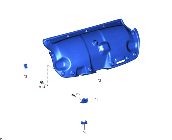
| *1 | DOOR CONTROL SWITCH | *2 | LUGGAGE COMPARTMENT DOOR COVER |
| *3 | LUGGAGE LOCK CONTROL CABLE PLATE | *4 | SWITCH BEZEL |
Removal
REMOVAL
PROCEDURE
1. REMOVE LUGGAGE LOCK CONTROL CABLE PLATE
Click here .gif)
2. REMOVE SWITCH BEZEL
Click here
3. REMOVE LUGGAGE COMPARTMENT DOOR COVER
Click here
4. REMOVE DOOR CONTROL SWITCH
| (a) Disconnect the connector. |
|
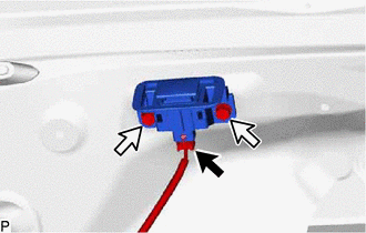
(b) Remove the 2 screws.
(c) Disengage the claw to remove the door control switch as shown in the illustration.

.png) | Remove in this Direction |
Inspection
INSPECTION
PROCEDURE
1. INSTALL DOOR CONTROL SWITCH
| (a) Check the resistance. (1) Measure the resistance according to the value(s) in the table below. Standard Resistance:
If the result is not as specified, replace the door control switch. |
|
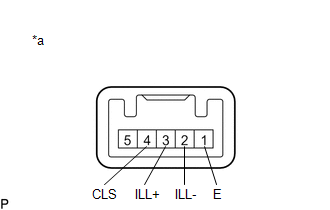
(b) Inspect the illumination operation.
(1) Apply auxiliary battery voltage to the switch connector and check that the door control switch illuminates.
OK:
| Tester Connection | Specified Condition |
|---|---|
| Auxiliary battery positive (+) → Terminal 3 (ILL+) Auxiliary battery negative (-) → Terminal 2 (ILL-) | Illumination illuminates |
If the result is not as specified, replace the door control switch.
Installation
INSTALLATION
PROCEDURE
1. INSTALL DOOR CONTROL SWITCH
(a) Engage the claw as shown in the illustration.
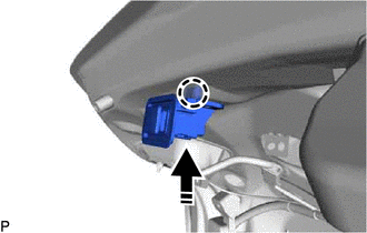
.png) | Install in this Direction |
(b) Install the door control switch with the 2 screws.
(c) Connect the connector.
2. INSTALL LUGGAGE COMPARTMENT DOOR COVER
Click here .gif)
3. INSTALL SWITCH BEZEL
Click here
4. INSTALL LUGGAGE LOCK CONTROL CABLE PLATE
Click here
READ NEXT:
 Components
COMPONENTS ILLUSTRATION *1 COWL SIDE TRIM BOARD LH *2 FRONT DOOR OPENING TRIM COVER LH *3 FRONT DOOR SCUFF PLATE LH *4 INSTRUMENT SIDE PANEL LH *5 LOWER INSTRUMENT PANEL FINI
Removal
REMOVAL PROCEDURE 1. REMOVE FRONT DOOR SCUFF PLATE LH Click here 2. REMOVE COWL SIDE TRIM BOARD LH Click here 3. REMOVE FRONT DOOR OPENING TRIM COVER LH Click here 4. REMOVE INSTRUMENT SIDE P
SEE MORE:
Lost Communication with Cruise Control Front Distance Range Sensor Signal Sensor or Center Missing Message (U023587)
DESCRIPTION The forward recognition camera and millimeter wave radar sensor assembly communicate via CAN communication. If there is an error in the communication with the millimeter wave radar sensor assembly, the forward recognition camera stores DTC U023587. DTC No. Detection Item DTC Detec
Disassembly
DISASSEMBLY CAUTION / NOTICE / HINT The necessary procedures (adjustment, calibration, initialization or registration) that must be performed after parts are removed and installed, or replaced during engine unit removal/installation are shown below. Necessary Procedure After Parts Removed/Installed/
