Lexus ES manuals

Lexus ES: Installation

INSTALLATION

PROCEDURE

1. INSTALL INVERTER WATER PUMP ASSEMBLY

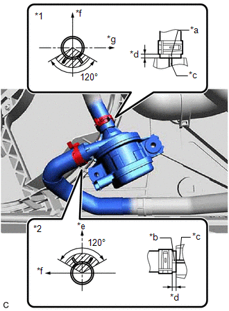
(a) Connect the No. 2 inverter cooling hose and No. 3 inverter cooling hose to the inverter water pump assembly and slide the 2 clips to secure them.

NOTICE:

  • Make sure to align the alignment marks of the hoses with the ribs of the inverter water pump assembly.
  • To prevent foreign matter from entering the inverter water pump assembly and inverter cooling system, do not remove the pieces of cloth from the pipes and disconnected hoses until installation.
  • If the inverter water pump assembly has been struck or dropped, replace it.

HINT:

Make sure that the clips are positioned as shown in the illustration.

*1

No. 2 Inverter Cooling Hose

*2

No. 3 Inverter Cooling Hose

*a

Alignment Mark (Red)

*b

Alignment Mark (Green)

*c

Rib

*d

2 to 7 mm (0.0787 to 0.276 in.)

*e

Up

*f

Front of Vehicle

*g

RH Side

(b) Temporarily install the inverter water pump assembly to the fan shroud assembly with the 2 bolts.

(c) Fully tighten the 2 bolts.

Torque:

7.0 N·m {71 kgf·cm, 62 in·lbf}

NOTICE:

As overtightening the bolts may damage the fan shroud assembly, make sure to use a torque wrench.

(d) Connect the inverter water pump assembly connector.

NOTICE:

If a dustproof cap is installed to the inverter water pump assembly connector, do not remove it until the connector is to be connected.

2. ADD COOLANT (for Inverter)

Click here

3. INSPECT FOR COOLANT LEAK (for Inverter)

Click here

4. INSTALL NO. 1 ENGINE UNDER COVER

Click here

5. INSTALL FRONT WHEEL OPENING EXTENSION PAD LH

Click here

6. INSTALL FRONT WHEEL OPENING EXTENSION PAD RH

Click here

READ NEXT:

 Power Source & Network

h1 {color:red;} h2 {color:blue;} h3 {color:green;}

 Power Distribution

 Main Body Ecu

SEE MORE:

 Rough Idling (P160500)

DESCRIPTION This DTC is stored if the combustion state of any cylinder is unstable. Using the Techstream, the conditions present when the DTC was stored can be confirmed by referring to the freeze frame data. Freeze frame data records engine conditions when a malfunction occurs. This information can

 Transmission Fluid Temperature Sensor "A" Circuit Short To Ground (P071011)

DESCRIPTION The ATF temperature sensor converts the automatic transaxle fluid (ATF) temperature into a resistance value for use by the ECM. The ECM applies voltage to the temperature sensor through terminal THO1 of the ECM. The sensor resistance changes with the ATF temperature. As the temperature r

© 2016-2026 Copyright www.lexguide.net