Lexus ES: Installation
INSTALLATION
CAUTION / NOTICE / HINT
NOTICE:
This procedure includes the installation of small-head bolts. Refer to Small-Head Bolts of Basic Repair Hint to identify the small-head bolts.
Click here .gif)
PROCEDURE
1. INSTALL NO. 3 EXHAUST MANIFOLD HEAT INSULATOR
(a) Type A:
(1) Install the No. 3 exhaust manifold heat insulator to the cylinder block sub-assembly with the bolt.
Torque:
16 N·m {163 kgf·cm, 12 ft·lbf}
(b) Type B:
(1) Install the No. 3 exhaust manifold heat insulator to the cylinder block sub-assembly with the 2 bolts.
Torque:
16 N·m {163 kgf·cm, 12 ft·lbf}
2. INSTALL ENGINE OIL LEVEL DIPSTICK GUIDE
(a) Apply a light coat of engine oil to a new O-ring.
(b) Install the O-ring to the engine oil level dipstick guide.
(c) Using an 8 mm socket wrench, install the engine oil level dipstick guide to the camshaft housing sub-assembly with the bolt.
Torque:
10 N·m {102 kgf·cm, 7 ft·lbf}
(d) Install the engine oil level dipstick.
3. INSTALL IGNITION COIL ASSEMBLY
Click here
4. INSTALL DIRECT FUEL INJECTOR ASSEMBLY
Click here
5. INSTALL FUEL DELIVERY PIPE
Click here
6. INSTALL PORT FUEL INJECTOR ASSEMBLY
Click here
7. INSTALL NO. 5 ENGINE WIRE
Click here
8. INSTALL INJECTOR VIBRATION INSULATOR
Click here
9. INSTALL NO. 1 DELIVERY PIPE SPACER
Click here
10. INSTALL FUEL DELIVERY PIPE SUB-ASSEMBLY
Click here
11. INSTALL WIRE HARNESS CLAMP BRACKET
(a) Using an 8 mm socket wrench, install the wire harness clamp bracket to the No. 1 ventilation case with the 2 bolts.
Torque:
10 N·m {102 kgf·cm, 7 ft·lbf}
12. INSTALL NO. 6 ENGINE WIRE
(a) Install the No. 6 engine wire to the wire harness clamp bracket with the 2 nuts.
Torque:
10 N·m {102 kgf·cm, 7 ft·lbf}
(b) Engage the 2 clamps.
(c) Connect the 4 connectors.
13. INSTALL SENSOR WIRE
(a) Using an 8 mm socket wrench, install the sensor wire to the water inlet with thermostat sub-assembly with the bolt.
Torque:
10 N·m {102 kgf·cm, 7 ft·lbf}
(b) Engage the 3 clamps.
(c) Connect the 4 connectors.
14. INSTALL NO. 7 WATER BY-PASS HOSE
(a) Install the No. 7 water by-pass hose and slide the 2 clips to secure it.
15. TEMPORARILY INSTALL FUEL (ENGINE ROOM SIDE) PUMP ASSEMBLY (for High Pressure)
Click here
16. TEMPORARILY INSTALL NO. 1 FUEL PIPE SUB-ASSEMBLY
Click here
17. INSTALL FUEL (ENGINE ROOM SIDE) PUMP ASSEMBLY (for High Pressure)
Click here
18. INSTALL NO. 1 FUEL PIPE SUB-ASSEMBLY
(a) for EGR Valve Bracket Connection Type:
| (1) Using a 17 mm union nut wrench, tighten the union nut on the fuel delivery pipe side of the No. 1 fuel pipe sub-assembly. Torque: Specified tightening torque : 35 N·m {357 kgf·cm, 26 ft·lbf} NOTICE: Do not adjust the torque in the loosening direction. HINT:
|
|
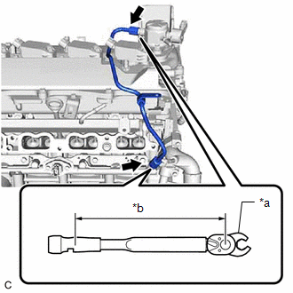
(2) Using a 17 mm union nut wrench, tighten the union nut on the fuel pump assembly side of the No. 1 fuel pipe sub-assembly.
Torque:
Specified tightening torque :
35 N·m {357 kgf·cm, 26 ft·lbf}
NOTICE:
Do not adjust the torque in the loosening direction.
HINT:
-
Calculate the torque wrench reading when changing the fulcrum length of the torque wrench.
Click here
- When using a 17 mm union nut wrench (fulcrum length of 30 mm (1.18 in.)) + torque wrench (fulcrum length of 180 mm (7.09 in.)): 30 N*m (306 kgf*cm, 22 ft.*lbf)
(b) for Cylinder Head Cover Sub-assembly Connection Type:
| (1) Using a 17 mm union nut wrench, tighten the union nut on the fuel delivery pipe side of the No. 1 fuel pipe sub-assembly. Torque: Specified tightening torque : 35 N·m {357 kgf·cm, 26 ft·lbf} NOTICE: Do not adjust the torque in the loosening direction. HINT:
|
|
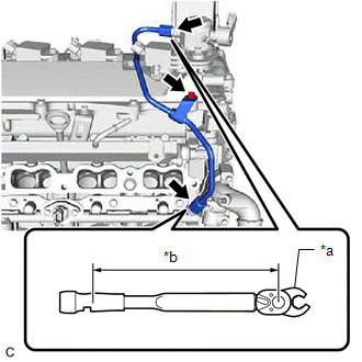
(2) Using a 17 mm union nut wrench, tighten the union nut on the fuel pump assembly side of the No. 1 fuel pipe sub-assembly.
Torque:
Specified tightening torque :
35 N·m {357 kgf·cm, 26 ft·lbf}
NOTICE:
Do not adjust the torque in the loosening direction.
HINT:
-
Calculate the torque wrench reading when changing the fulcrum length of the torque wrench.
Click here
- When using a 17 mm union nut wrench (fulcrum length of 30 mm (1.18 in.)) + torque wrench (fulcrum length of 180 mm (7.09 in.)): 30 N*m (306 kgf*cm, 22 ft.*lbf)
(3) Using an 8 mm socket wrench, install the bolt.
Torque:
10 N·m {102 kgf·cm, 7 ft·lbf}
19. CONNECT FUEL TUBE SUB-ASSEMBLY
Click here
20. INSTALL NO. 1 INTAKE MANIFOLD TO HEAD GASKET
Click here
21. INSTALL INTAKE MANIFOLD
Click here
22. INSTALL NO. 2 WATER BY-PASS PIPE
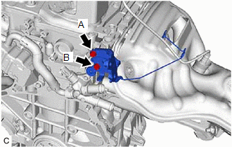
| (a) Temporarily install the No. 2 water by-pass pipe to the cylinder block sub-assembly with the bolt (A). |
|
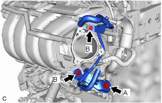
(b) Using an 8 mm socket wrench, temporarily install the No. 2 water by-pass pipe to the intake manifold with the 2 bolts (B).
(c) Tighten the bolt (A).
Torque:
21 N·m {214 kgf·cm, 15 ft·lbf}
(d) Using an 8 mm socket wrench, tighten the 2 bolts (B).
Torque:
10 N·m {102 kgf·cm, 7 ft·lbf}
23. INSTALL NO. 3 WATER BY-PASS PIPE
(a) Connect the No. 3 water by-pass pipe to the water outlet and slide the clip to secure it.
(b) Using an 8 mm socket wrench, install the No. 3 water by-pass pipe to the intake manifold with the bolt.
Torque:
10 N·m {102 kgf·cm, 7 ft·lbf}
24. INSTALL EGR VALVE ASSEMBLY
(a) Using an 8 mm socket wrench, install the EGR valve bracket with the bolt.
Torque:
10 N·m {102 kgf·cm, 7 ft·lbf}
(b) for EGR Valve Bracket Connection Type:
| (1) Align and fit the hole of the EGR valve bracket to the pin of the camshaft housing sub-assembly. |
|
.png)
(2) Using an 8 mm socket wrench, install the EGR valve assembly with the EGR valve bracket to the camshaft housing sub-assembly with the bolt.
Torque:
10 N·m {102 kgf·cm, 7 ft·lbf}
(3) Using an 8 mm socket wrench, connect the No. 1 fuel pipe sub-assembly to the EGR valve bracket with the bolt.
Torque:
10 N·m {102 kgf·cm, 7 ft·lbf}
(c) for Cylinder Head Cover Sub-assembly Connection Type:
| (1) Align and fit the hole of the EGR valve bracket to the pin of the camshaft housing sub-assembly. |
|
(2) Using an 8 mm socket wrench, install the EGR valve assembly with the EGR valve bracket to the camshaft housing sub-assembly with the bolt.
Torque:
10 N·m {102 kgf·cm, 7 ft·lbf}
(d) Connect the No. 8 water by-pass hose to the EGR valve assembly and slide the clip to secure it.
25. INSTALL NO. 4 WATER BY-PASS HOSE
(a) Install the No. 4 water by-pass hose to the EGR valve assembly and slide the clip to secure it.
26. INSTALL NO. 1 EGR PIPE SUB-ASSEMBLY
Click here
27. INSTALL EGR COOLER ASSEMBLY
(a) Install the EGR cooler assembly, a new EGR cooler gasket and EGR valve gasket with the 5 bolts.
Torque:
24 N·m {245 kgf·cm, 18 ft·lbf}
(b) Connect the No. 3 water by-pass hose to the EGR cooler assembly and slide the clip to secure it.
(c) Connect the No. 4 water by-pass hose to the EGR cooler assembly and slide the clip to secure it.
28. INSTALL THROTTLE BODY GASKET
Click here
29. INSTALL THROTTLE BODY WITH MOTOR ASSEMBLY
Click here
30. INSTALL EXHAUST MANIFOLD (TWC: Front Catalyst)
Click here
31. INSTALL MANIFOLD STAY
Click here
32. INSTALL NO. 1 EXHAUST MANIFOLD HEAT INSULATOR
(a) Type A:
(1) Install the No. 1 exhaust manifold heat insulator to the exhaust manifold (TWC: Front Catalyst) with the 5 bolts.
Torque:
10 N·m {102 kgf·cm, 7 ft·lbf}
(b) Type B:
(1) Install the No. 1 exhaust manifold heat insulator to the exhaust manifold (TWC: Front Catalyst) with the 3 bolts.
Torque:
10 N·m {102 kgf·cm, 7 ft·lbf}
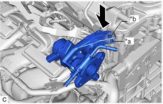
33. INSTALL FLOW SHUTTING VALVE (WATER BY-PASS HOSE ASSEMBLY)
| (a) Install the water hose clamp bracket with the 2 bolts as shown in the illustration. Torque: 13 N·m {133 kgf·cm, 10 ft·lbf} NOTICE: Temporarily tighten the bolt (A), and then fully tighten the 2 bolts in the order of (B) and (A). |
|
| (b) Connect the flow shutting valve (water by-pass hose assembly) to the water by-pass outlet sub-assembly and slide the clip to secure it. NOTICE:
|
|
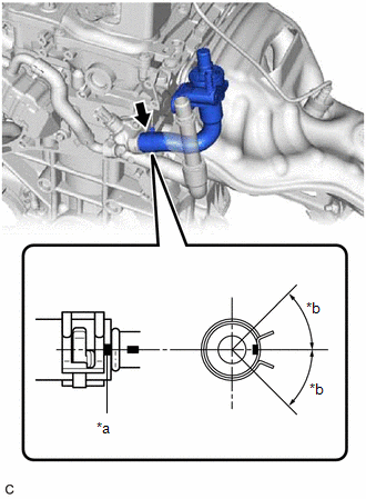
(c) Install the flow shutting valve (water by-pass hose assembly) with the bolt.
Torque:
19 N·m {194 kgf·cm, 14 ft·lbf}
34. INSTALL NO. 2 WATER BY-PASS PIPE SUB-ASSEMBLY
(a) Install the No. 2 water by-pass pipe sub-assembly with the bolt.
Torque:
19 N·m {194 kgf·cm, 14 ft·lbf}
(b) Connect the No. 2 water by-pass pipe sub-assembly to the outlet water by-pass sub-assembly and slide the clip to secure it.
35. INSTALL COMPRESSOR WITH MOTOR ASSEMBLY
(a) Using an E8 "TORX" socket wrench, temporarily install the compressor with motor assembly with the 2 stud bolts.
Torque:
5.0 N·m {51 kgf·cm, 44 in·lbf}
(b) Install the compressor with motor assembly with the bolt and 2 nuts.
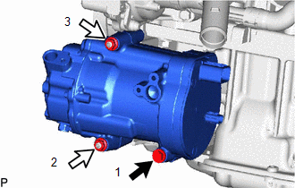
.png) | Bolt |
.png) | Nut |
Torque:
24.5 N·m {250 kgf·cm, 18 ft·lbf}
HINT:
Tighten the bolt and nuts in the order shown in the illustration.
36. INSTALL DRIVE SHAFT BEARING BRACKET
(a) Install the drive shaft bearing bracket with the 3 bolts.
Torque:
63.7 N·m {650 kgf·cm, 47 ft·lbf}
READ NEXT:
 Components
COMPONENTS ILLUSTRATION *1 CRANKSHAFT PULLEY ASSEMBLY *2 TIMING CHAIN COVER OIL SEAL *3 CRANKSHAFT PULLEY BOLT - - N*m (kgf*cm, ft.*lbf): Specified torque ● Non-reusab
Removal
REMOVAL CAUTION / NOTICE / HINT The necessary procedures (adjustment, calibration, initialization, or registration) that must be performed after parts are removed and installed, or replaced during fro
SEE MORE:
High Voltage System Interlock Circuit Open (P0A0A13,P0A0A92)
DTC SUMMARY MALFUNCTION DESCRIPTION The hybrid vehicle control ECU detects that a safety device (interlock) is operated or that there is an open circuit in the detection circuit. (Even if an open circuit occurs while the vehicle is stopped, the system determines that the safety device was operated.)
System Diagram
SYSTEM DIAGRAM (a) The CAN communication system is composed of 5 buses. CAN Main Bus Line Terminating Resistor CAN Branch Line * Gateway Function Equipped ECU Bus Monitoring Direction - - Connected to Code ECU/Sensor Name CAN DTC Storage Note - C
