Lexus ES: Installation
INSTALLATION
CAUTION / NOTICE / HINT
CAUTION:
- The engine assembly with transaxle is very heavy. Be sure to follow the procedure described in the repair manual, or the engine lifter may suddenly drop or the engine assembly with transaxle may fall off the engine lifter.
- To prevent burns, do not touch the engine, exhaust manifold or other high temperature components while the engine is hot.
PROCEDURE
1. INSTALL ENGINE MOUNTING INSULATOR LH
HINT:
Perform this procedure only when replacement of the engine mounting insulator LH is necessary.
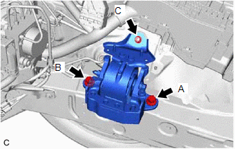
| (a) Install the engine mounting insulator LH with the 2 bolts and nut. Torque: 72 N·m {734 kgf·cm, 53 ft·lbf} NOTICE: Temporarily tighten the bolt (A), and then fully tighten the 2 bolts and nut in the order of (B), (A) and (C). |
|
2. INSTALL ENGINE MOUNTING SPACER
HINT:
Perform this procedure only when replacement of the engine mounting spacer is necessary.
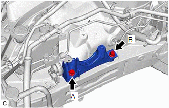
| (a) Install the engine mounting spacer to the vehicle body with the 2 bolts. Torque: 72 N·m {734 kgf·cm, 53 ft·lbf} NOTICE: Temporarily tighten the bolt (A), and then fully tighten the 2 bolts in the order of (B) and (A). |
|
3. INSTALL ENGINE MOUNTING INSULATOR SUB-ASSEMBLY RH
HINT:
Perform this procedure only when replacement of the engine mounting insulator sub-assembly RH is necessary.
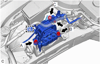
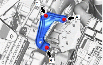
| (a) Install the engine mounting insulator sub-assembly RH with the 2 bolts and nut. Torque: 72 N·m {734 kgf·cm, 53 ft·lbf} NOTICE: Temporarily tighten the bolt (A), and then fully tighten the 2 bolts and nut in the order of (B), (A) and (C). |
|
(b) Connect the cooler bracket to the engine mounting insulator sub-assembly RH with the bolt.
Torque:
9.8 N·m {100 kgf·cm, 87 in·lbf}
(c) Engage the clamp.
(d) Connect the No. 2 earth wire to the engine mounting insulator sub-assembly RH with the bolt.
Torque:
9.5 N·m {97 kgf·cm, 84 in·lbf}
(e) Install the radiator reserve tank assembly with the bolt and nut.
Torque:
5.0 N·m {51 kgf·cm, 44 in·lbf}
(f) Engage the No. 6 water by-pass hose.
4. INSTALL ENGINE HANGERS
Click here .gif)
5. REMOVE ENGINE ASSEMBLY FROM ENGINE STAND
(a) Remove the engine assembly from the engine stand.
6. INSTALL NO. 1 CRANKSHAFT POSITION SENSOR PLATE
Click here
7. INSTALL FLYWHEEL SUB-ASSEMBLY
Click here
8. INSTALL TRANSMISSION INPUT DAMPER ASSEMBLY
Click here
9. INSTALL HYBRID VEHICLE TRANSAXLE ASSEMBLY
Click here
10. INSTALL FLYWHEEL HOUSING SIDE COVER
Click here
11. INSTALL STARTER HOLE INSULATOR
Click here
12. INSTALL HV AIR CONDITIONING WIRE
(a) Engage the guide to install the HV air conditioning wire to the hybrid vehicle transaxle assembly.
(b) Install the bolt.
Torque:
20 N·m {204 kgf·cm, 15 ft·lbf}
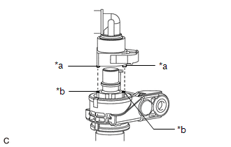
(c) Connect the connector and slide the green-colored lock as shown in the illustration to lock it securely.
CAUTION:
Make sure to wear insulated gloves.
NOTICE:
Make sure that the connector is connected securely.
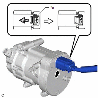
| *a | Green-colored Lock |
.png) | Slide |
(d) Engage the 2 clamps.
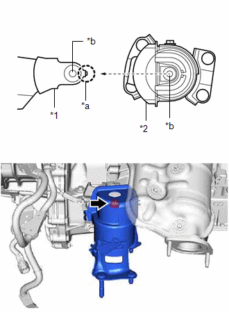
13. INSTALL REAR ENGINE MOUNTING INSULATOR
HINT:
Perform this procedure only when replacement of the rear engine mounting insulator is necessary.
| (a) Align the hole of the rear engine mounting insulator with the protrusion of the rear engine mounting bracket, slide the rear engine mounting insulator onto the rear engine mounting bracket to align the holes and install the rear engine mounting insulator with the bolt. Torque: 72 N·m {734 kgf·cm, 53 ft·lbf} |
|
14. INSTALL FRONT ENGINE MOUNTING INSULATOR
HINT:
Perform this procedure only when replacement of the front engine mounting insulator is necessary.
Click here
15. INSTALL FRONT FRAME ASSEMBLY
Click here
16. INSTALL ENGINE WIRE
(a) Connect all connectors and clamps, and install the engine wire to the engine assembly with transaxle.
17. INSTALL STEERING GEAR HEAT INSULATOR
Click here
18. INSTALL FLYWHEEL HOUSING UNDER COVER
(a) Install the flywheel housing under cover to the cylinder block sub-assembly.
19. INSTALL ENGINE ASSEMBLY WITH TRANSAXLE
HINT:
Perform inspection after repair after replacing the engine assembly.
Click here
(a) Set the engine assembly with transaxle on an engine lifter.
NOTICE:
- Using height adjustment attachments and plate lift attachments, keep the engine assembly with transaxle level.
- Do not perform any procedures while the engine assembly is suspended because doing so may cause the engine assembly to drop, resulting in injury. However, the engine assembly needs to be suspended when it is installed to or removed from an engine stand.
(b) Remove the 4 bolts, No. 1 engine hanger and No. 2 engine hanger from the cylinder head sub-assembly and engine mounting bracket RH.
(c) Install the fuel delivery guard to the engine mounting bracket RH with the bolt.
Torque:
40 N·m {408 kgf·cm, 30 ft·lbf}
(d) Operate the engine lifter and install the engine assembly with transaxle to the vehicle.
CAUTION:
Do not raise the engine assembly with transaxle more than necessary. If the engine is raised excessively, the vehicle may also be lifted up.
NOTICE:
- Make sure that the engine assembly with transaxle is clear of all wiring and hoses.
- While raising the engine assembly with transaxle into the vehicle, do not allow it to contact the vehicle.
(e) w/o Suspension Tower Damper:
(1) Install the front bumper extension sub-assembly RH and front bumper extension sub-assembly LH to the front frame assembly and vehicle body with the 8 bolts.
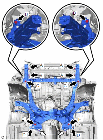
.png) | Bolt |
.png) | Nut |
Torque:
Bolt (A) :
9.0 N·m {92 kgf·cm, 80 in·lbf}
Bolt (B) :
12.5 N·m {127 kgf·cm, 9 ft·lbf}
Bolt (C) :
135 N·m {1377 kgf·cm, 100 ft·lbf}
(2) Install the front suspension member bracket sub-assembly RH and front suspension member bracket sub-assembly LH to the front frame assembly and vehicle body with the 4 bolts and 2 nuts.
Torque:
Bolt (D) :
17.5 N·m {178 kgf·cm, 13 ft·lbf}
Bolt (E) :
135 N·m {1377 kgf·cm, 100 ft·lbf}
Nut :
17.5 N·m {178 kgf·cm, 13 ft·lbf}
(f) w/ Suspension Tower Damper:
(1) Install the front bumper extension sub-assembly RH and front bumper extension sub-assembly LH to the front frame assembly and vehicle body with the 6 bolts.
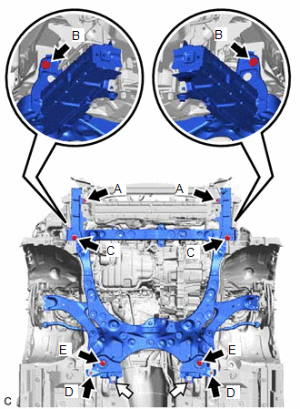
| | Bolt |
| | Nut |
Torque:
Bolt (A) :
9.0 N·m {92 kgf·cm, 80 in·lbf}
Bolt (B) :
12.5 N·m {127 kgf·cm, 9 ft·lbf}
Bolt (C) :
135 N·m {1377 kgf·cm, 100 ft·lbf}
(2) Install the front suspension member bracket sub-assembly RH and front suspension member bracket sub-assembly LH to the front frame assembly and vehicle body with the 4 bolts and 2 nuts.
Torque:
Bolt (D) :
17.5 N·m {178 kgf·cm, 13 ft·lbf}
Bolt (E) :
135 N·m {1377 kgf·cm, 100 ft·lbf}
Nut :
17.5 N·m {178 kgf·cm, 13 ft·lbf}
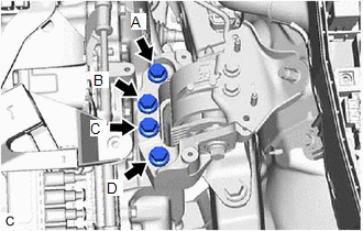
| (g) Install the engine mounting insulator LH to the hybrid vehicle transaxle assembly with the 4 bolts. Torque: 42 N·m {428 kgf·cm, 31 ft·lbf} NOTICE: Fully tighten the 4 bolts in the order of (A), (C), (B) and (D). |
|
| (h) Install the engine mounting stay LH to the engine mounting insulator LH with the 3 bolts. Torque: 8.0 N·m {82 kgf·cm, 71 in·lbf} NOTICE: Temporarily tighten the bolt (A), and then fully tighten the 3 bolts in the order of (B), (C) and (A). |
|
(i) Install the engine mounting insulator sub-assembly RH to the engine mounting bracket RH with the 3 bolts and nut.
Torque:
Bolt :
72 N·m {734 kgf·cm, 53 ft·lbf}
Nut :
42 N·m {428 kgf·cm, 31 ft·lbf}
(j) Install the body mounting plate with the 6 bolts.
Torque:
17.5 N·m {178 kgf·cm, 13 ft·lbf}
20. INSTALL SUSPENSION TOWER DAMPER (w/ Suspension Tower Damper)
Click here
21. INSTALL FRONT DRIVE SHAFT ASSEMBLY
Click here
22. INSTALL FRONT EXHAUST PIPE ASSEMBLY (TWC: Rear Catalyst)
Click here
23. CONNECT STEERING INTERMEDIATE SHAFT ASSEMBLY
Click here
24. CONNECT NO. 5 WATER BY-PASS HOSE
(a) Connect the No. 5 water by-pass hose to the No. 3 water by-pass pipe and slide the clip to secure it.
25. CONNECT WIRE HARNESS
(a) Engage the earth wire with the 2 bolts.
Torque:
10 N·m {102 kgf·cm, 7 ft·lbf}
(b) Engage the claw to connect the wire harness to the engine room relay block and junction block assembly.
(c) Connect the 5 connectors to the engine room relay block and junction block assembly.
(d) Install the nut to the engine room relay block and junction block assembly.
Torque:
8.0 N·m {82 kgf·cm, 71 in·lbf}
(e) Install the No. 2 relay block cover to the engine room relay block and junction block assembly.
26. CONNECT NO. 5 INVERTER COOLING HOSE
(a) Connect the No. 5 inverter cooling hose to the motor cooling cooler and slide the clip to secure it.
27. CONNECT SUCTION HOSE
Click here
28. CONNECT NO. 1 COOLER REFRIGERANT DISCHARGE HOSE
Click here
29. CONNECT NO. 2 RADIATOR HOSE
(a) Connect the No. 2 radiator hose to the water inlet and slide the clip to secure it.
30. CONNECT NO. 1 RADIATOR HOSE
(a) Connect the No. 1 radiator hose to the front engine mounting bracket with the bolt.
Torque:
19 N·m {194 kgf·cm, 14 ft·lbf}
(b) Connect the No. 1 radiator hose to the water outlet and slide the clip to secure it.
31. INSTALL NO. 2 ENGINE COOLANT TEMPERATURE SENSOR
Click here
32. CONNECT FUEL TUBE SUB-ASSEMBLY
(a) Connect the fuel tube sub-assembly.
(1) Connect the fuel tube sub-assembly to the fuel pipe.
Click here
(b) Install the EFI fuel pipe clamp to the fuel tube connector.
33. CONNECT INLET HEATER HOSE
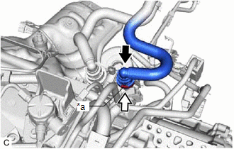
| (a) Align the protrusions of the inlet heater hose connector with the cutouts in the flow shutting valve (water by-pass hose assembly) and push them together until the inlet heater hose connector makes a "click" sound. |
|
(b) Push in the retainer.
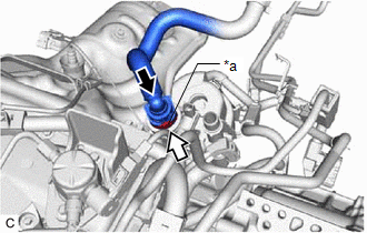
| *a | Retainer |
| | Push |
| | Push in |
(c) Check that the flow shutting valve (water by-pass hose assembly) and inlet heater hose connector are securely connected by pulling on them.
34. CONNECT OUTLET HEATER HOSE
| (a) Align the protrusion of the No. 2 water by-pass pipe sub-assembly with the cutout in the outlet heater hose connector and push them together until the outlet heater hose makes a "click" sound. |
|
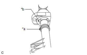
(b) Push in the retainer.
| *a | Retainer |
| | Push |
| | Push in |
(c) Check that the No. 2 water by-pass pipe sub-assembly and outlet heater hose connector are securely connected by pulling on them.
35. CONNECT NO. 1 FUEL VAPOR FEED HOSE
(a) Connect the No. 1 fuel vapor feed hose to the No. 1 vacuum switching valve assembly and slide the clip to secure it.
36. INSTALL INVERTER RESERVE TANK ASSEMBLY
| (a) Connect the No. 2 inverter cooling hose to the inverter reserve tank assembly and slide the clip to secure it. |
|
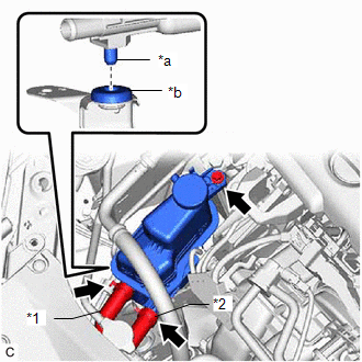
(b) Connect the No. 5 inverter cooling hose to the inverter reserve tank assembly and slide the clip to secure it.
(c) Fit the pin of the inverter reserve tank assembly into grommet as shown in the illustration.
(d) Install the inverter reserve tank assembly with the bolt.
Torque:
5.0 N·m {51 kgf·cm, 44 in·lbf}
37. INSTALL INVERTER WITH CONVERTER ASSEMBLY
Click here
38. INSTALL FRONT LOWER BUMPER ABSORBER
(a) Engage the 2 claws to install the front lower bumper absorber.
(b) Install the 4 bolts.
Torque:
7.5 N·m {76 kgf·cm, 66 in·lbf}
39. INSTALL HEADLIGHT ASSEMBLY
-
for LED Type Turn Signal Light:
Click here
-
for Bulb Type Turn Signal Light:
Click here
40. INSTALL FRONT FENDER APRON SEAL LH
(a) Install the front fender apron seal LH with the 2 screws and clip.
Torque:
7.5 N·m {76 kgf·cm, 66 in·lbf}
41. INSTALL FRONT FENDER APRON SEAL RH
(a) Install the front fender apron seal RH with the 2 screws and clip.
Torque:
7.5 N·m {76 kgf·cm, 66 in·lbf}
42. INSTALL NO. 2 ENGINE UNDER COVER ASSEMBLY
(a) Install the No. 2 engine under cover assembly with the 4 screws and 6 clips.
Torque:
7.5 N·m {76 kgf·cm, 66 in·lbf}
43. INSTALL NO. 1 ENGINE UNDER COVER
(a) Install the No. 1 engine under cover with the bolt, 6 screws and 2 clips.
Torque:
Bolt :
7.5 N·m {76 kgf·cm, 66 in·lbf}
44. INSTALL FRONT WHEEL OPENING EXTENSION PAD LH
(a) Install the front wheel opening extension pad LH with the 3 screws.
45. INSTALL FRONT WHEEL OPENING EXTENSION PAD RH
(a) Install the front wheel opening extension pad RH with the 3 screws.
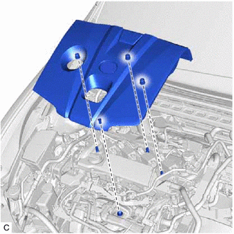
46. INSTALL NO. 1 ENGINE COVER SUB-ASSEMBLY
| (a) Engage the 4 clips to install the No. 1 engine cover sub-assembly. NOTICE:
|
|
47. ADD ENGINE OIL
Click here
48. ADD HYBRID TRANSAXLE FLUID
Click here
49. ADD ENGINE COOLANT (for Engine)
Click here
50. CHARGE AIR CONDITIONING SYSTEM WITH REFRIGERANT
Click here
51. WARM UP COMPRESSOR
Click here
52. INSPECT SHIFT LEVER POSITION
Click here
53. ADJUST SHIFT LEVER POSITION
Click here
54. INSPECT FOR ENGINE OIL LEAK
Click here
55. INSPECT FOR COOLANT LEAK (for Engine)
Click here
56. INSPECT FOR REFRIGERANT LEAK
Click here
57. INSPECT FOR FUEL LEAK
Click here
58. INSPECT FOR EXHAUST GAS LEAK
Click here
59. CHECK ENGINE OIL LEVEL
Click here
60. INSPECT HYBRID TRANSAXLE FLUID
Click here
61. INSPECT ENGINE COOLANT LEVEL IN RESERVOIR TANK
Click here
62. INSTALL FRONT WHEELS
Click here
63. ALIGN FRONT WHEELS FACING STRAIGHT AHEAD
64. INSPECT AND ADJUST FRONT WHEEL ALIGNMENT
Click here
65. PERFORM INITIALIZATION
Click here
66. INSPECT IGNITION TIMING
Click here
67. INSPECT ENGINE IDLE SPEED
Click here
68. INSPECT CO/HC
Click here
69. CHECK SPEED SENSOR SIGNAL
Click here
READ NEXT:
 Removal
REMOVAL CAUTION / NOTICE / HINT The necessary procedures (adjustment, calibration, initialization, or registration) that must be performed after parts are removed and installed, or replaced during eng
Components
COMPONENTS ILLUSTRATION *A Type A - - *1 EXHAUST MANIFOLD (TWC: Front Catalyst) *2 NO. 1 EXHAUST MANIFOLD HEAT INSULATOR *3 MANIFOLD STAY *4 EXHAUST MANIFOLD TO HEAD GASK
SEE MORE:
On-vehicle Inspection
ON-VEHICLE INSPECTION PROCEDURE 1. INSPECT PCV VALVE (VENTILATION VALVE SUB-ASSEMBLY) CAUTION: To prevent injury due to contact with an operating cooling fan, keep your hands and clothing away from the cooling fans when working in the engine compartment with the engine running or the power switch on
Stereo Component Amplifier Disconnected (B15D3)
DESCRIPTION The radio receiver assembly and stereo component amplifier assembly are connected by AVC-LAN communication lines. This DTC is stored when an AVC-LAN communication error occurs between the radio receiver assembly and stereo component amplifier assembly. DTC No. Detection Item DTC D
