Lexus ES: Installation
INSTALLATION
PROCEDURE
1. INSTALL FUEL VAPOR CONTAINMENT VALVE (FUEL TANK SOLENOID MAIN VALVE ASSEMBLY)
(a) Install the fuel vapor containment valve (fuel tank solenoid main valve assembly) to the vehicle body with the 2 nuts.
Torque:
8.0 N·m {82 kgf·cm, 71 in·lbf}
(b) Push the fuel tank vent hose onto the fuel vapor containment valve (fuel tank solenoid main valve assembly) and push in the retainer to engage the lock claws.
NOTICE:
- Check that there are no scratches or foreign matter around the connecting parts of the fuel tank vent hose and fuel vapor containment valve (fuel tank solenoid main valve assembly) before performing this work.
- After connecting the fuel tank vent hose, check that the fuel tank vent hose is securely connected by pulling on the fuel tank vent hose.
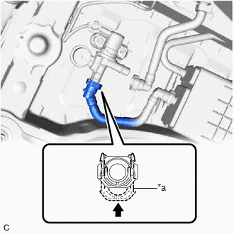
| *a | Retainer |
.png) | Push in |
(c) Connect the fuel vapor containment valve (fuel tank solenoid main valve assembly) connector.
(d) Push the fuel tank vent hose sub-assembly onto the fuel vapor containment valve (fuel tank solenoid main valve assembly) and push in the retainer to engage the lock claws.
NOTICE:
- Check that there are no scratches or foreign matter around the connecting parts of the fuel tank vent hose sub-assembly and fuel vapor containment valve (fuel tank solenoid main valve assembly) before performing this work.
- After connecting the fuel tank vent hose sub-assembly, check that the fuel tank vent hose sub-assembly is securely connected by pulling on the fuel tank vent hose sub-assembly.
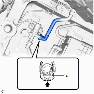
| *a | Retainer |
| | Push in |
READ NEXT:
 Components
COMPONENTS ILLUSTRATION *1 PCV VALVE (VENTILATION VALVE SUB-ASSEMBLY) - -
On-vehicle Inspection
ON-VEHICLE INSPECTION PROCEDURE 1. INSPECT PCV VALVE (VENTILATION VALVE SUB-ASSEMBLY) CAUTION: To prevent injury due to contact with an operating cooling fan, keep your hands and clothing away from th
SEE MORE:
System Description
SYSTEM DESCRIPTION HEATED STEERING WHEEL SYSTEM (a) The heated steering wheel system heats the steering wheel assembly when the system is turned on using the steering wheel heater switch (refreshing seat switch) or steering wheel heater switch (multi-display assembly). (b) The heated steering wheel
Mirror Heater does not Operate with Rear Defogger Switch
DESCRIPTION When the mirror heater switch (rear window defogger switch) is operated, the mirror heater signal is sent to the air conditioning amplifier assembly and then to each outer mirror control ECU assembly via CAN communication. Based on this signal, the outer mirror control ECU assemblies ope
© 2016-2026 Copyright www.lexguide.net
