Lexus ES: Components
COMPONENTS
ILLUSTRATION
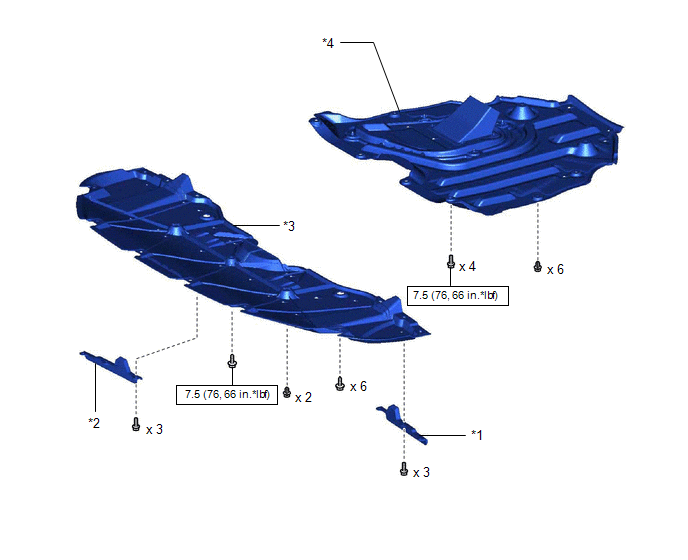
| *1 | FRONT WHEEL OPENING EXTENSION PAD LH | *2 | FRONT WHEEL OPENING EXTENSION PAD RH |
| *3 | NO. 1 ENGINE UNDER COVER | *4 | NO. 2 ENGINE UNDER COVER ASSEMBLY |
.png) | N*m (kgf*cm, ft.*lbf): Specified torque | - | - |
ILLUSTRATION
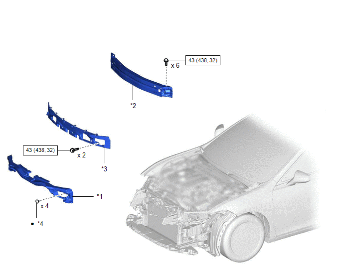
| *1 | FRONT BUMPER ENERGY ABSORBER | *2 | FRONT BUMPER REINFORCEMENT SUB-ASSEMBLY |
| *3 | NO. 2 FRONT BUMPER MOUNTING BRACKET | *4 | CLIP |
| | N*m (kgf*cm, ft.*lbf): Specified torque | ● | Non-reusable part |
ILLUSTRATION
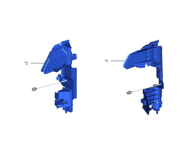
| *1 | NO. 1 RADIATOR AIR GUIDE LH | *2 | NO. 1 RADIATOR AIR GUIDE RH |
ILLUSTRATION
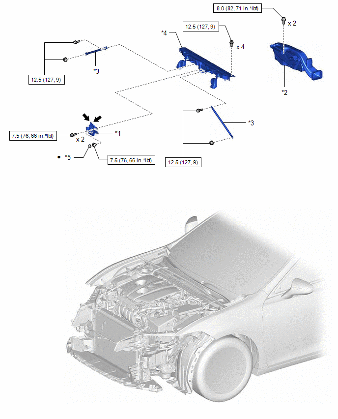
| *1 | HOOD LOCK ASSEMBLY | *2 | INLET AIR CLEANER ASSEMBLY |
| *3 | UPPER RADIATOR MOUNTING BRACKET | *4 | UPPER RADIATOR SUPPORT SUB-ASSEMBLY |
| *5 | HOOD LOCK NUT CAP | - | - |
| | N*m (kgf*cm, ft.*lbf): Specified torque | ● | Non-reusable part |
.png) | MP grease | - | - |
ILLUSTRATION
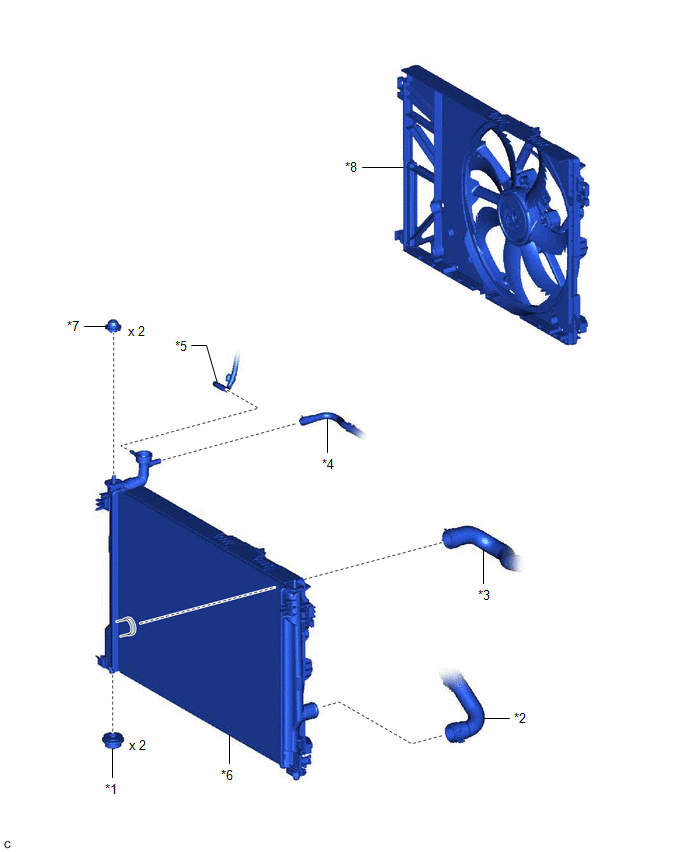
| *1 | LOWER RADIATOR SUPPORT | *2 | NO. 1 RADIATOR HOSE |
| *3 | NO. 2 RADIATOR HOSE | *4 | NO. 5 WATER BY-PASS HOSE |
| *5 | NO. 6 WATER BY-PASS HOSE | *6 | RADIATOR ASSEMBLY |
| *7 | RADIATOR SUPPORT CUSHION | *8 | FAN WITH MOTOR ASSEMBLY |
READ NEXT:
 On-vehicle Inspection
ON-VEHICLE INSPECTION CAUTION / NOTICE / HINT CAUTION: Do not remove the radiator cap sub-assembly while the engine and radiator assembly are still hot. Pressurized, hot engine coolant and steam may b
Removal
REMOVAL CAUTION / NOTICE / HINT The necessary procedures (adjustment, calibration, initialization or registration) that must be performed after parts are removed and installed, or replaced during radi
Installation
INSTALLATION PROCEDURE 1. INSTALL LOWER RADIATOR SUPPORT (a) Install the 2 lower radiator supports to the radiator assembly. 2. INSTALL RADIATOR SUPPORT CUSHION (a) Install the 2 radiator support cush
SEE MORE:
Inspection
INSPECTION PROCEDURE 1. INSPECT FRONT SHOCK ABSORBER ASSEMBLY (a) Compress and extend the front shock absorber assembly rod 4 times or more. Standard: When compressed and extended at a constant speed, the stroke of the shock absorber rod is smooth with no abnormal resistance or sounds. When extende
Knock Sensor
ComponentsCOMPONENTS ILLUSTRATION *1 KNOCK CONTROL SENSOR - - N*m (kgf*cm, ft.*lbf): Specified torque - - InspectionINSPECTION PROCEDURE 1. INSPECT KNOCK CONTROL SENSOR (a) Measure the resistance according to the value(s) in the table below. Standard Resistance: Test
