Lexus ES: Installation
INSTALLATION
CAUTION / NOTICE / HINT
CAUTION:
The engine assembly with transaxle is very heavy. Be sure to follow the procedure described in the repair manual, or the engine lifter may suddenly drop or the engine assembly with transaxle may fall off the engine lifter.
PROCEDURE
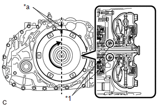
1. INSTALL TORQUE CONVERTER ASSEMBLY
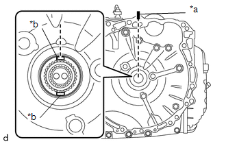
| (a) Set the key at the top of the front oil pump drive gear and put a matchmark on the transaxle housing. |
|
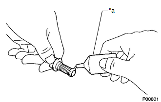
(b) Apply MP grease to place a matchmark on the torque converter assembly so that the position of its groove is clearly indicated.
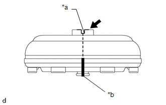
| *a | Groove |
| *b | Matchmark |
.png) | MP Grease |
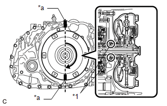
| (c) Align the matchmark on the transaxle housing with the one on the torque converter assembly and engage the splines of the input shaft with the turbine runner splines. NOTICE:
|
|
| (d) Rotate the torque converter assembly approximately 180° and engage the splines of the stator shaft with the stator assembly. NOTICE:
|
|
| (e) Rotate the torque converter assembly approximately 180° again, align the matchmark on the torque converter assembly with the one on the transaxle housing and insert the groove of the torque converter assembly into the key of the oil pump drive gear. NOTICE:
|
|
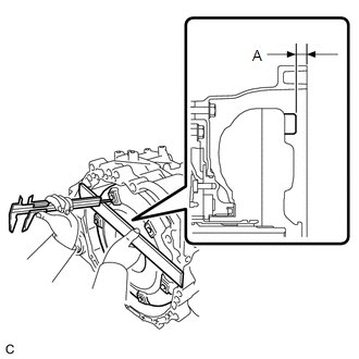
(f) Clean the drive plate and torque converter assembly setting bolt holes.
| (g) Using a vernier caliper and straightedge, measure the dimension (A) shown in the illustration and check the dimension (A). Standard: 14 mm (0.5512 in.) or more NOTICE:
|
|
2. INSTALL WIRE HARNESS CLAMP BRACKET
(a) Install the 2 wire harness clamp brackets to the automatic transaxle case sub-assembly with the 2 bolts.
Torque:
20 N·m {204 kgf·cm, 15 ft·lbf}
(b) Install the wire harness clamp bracket to the automatic transaxle case sub-assembly with the bolt.
Torque:
10 N·m {102 kgf·cm, 7 ft·lbf}
3. INSTALL TRANSMISSION CASE PLUG ASSEMBLY (for TMC Made)
(a) Coat a new O-ring with Toyota Genuine ATF WS and install it to the transmission case plug assembly.
(b) Install the transmission case plug assembly to the transaxle housing.
4. INSTALL TRANSMISSION CASE PLUG ASSEMBLY (for TMMWV Made)
(a) Coat the O-ring of a new transmission case plug assembly with Toyota Genuine ATF WS.
(b) Install the transmission case plug assembly to the transaxle housing.
5. INSTALL NO. 1 TRANSMISSION CONTROL CABLE BRACKET
(a) Install the No. 1 transmission control cable bracket to the automatic transaxle case sub-assembly with the 2 bolts.
Torque:
12 N·m {122 kgf·cm, 9 ft·lbf}
6. INSTALL AUTOMATIC TRANSMISSION CASE COVER
(a) Install the automatic transmission case cover to the automatic transaxle case sub-assembly with the 2 clips.
7. INSTALL TRANSMISSION OIL COOLER
Click here .gif)
8. INSTALL NO. 1 OIL COOLER TUBE SUB-ASSEMBLY WITHOUT HOSE
Click here
9. CONNECT INLET NO. 1 OIL COOLER HOSE
Click here
10. CONNECT OUTLET NO. 1 OIL COOLER HOSE
Click here
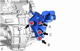
11. INSTALL REAR ENGINE MOUNTING BRACKET SUB-ASSEMBLY
| (a) Install the rear engine mounting bracket sub-assembly to the transaxle housing with the 4 bolts. Torque: 42 N·m {428 kgf·cm, 31 ft·lbf} HINT: Tightening order: Temporarily tighten bolt (A) → Fully tighten bolt (B) → Fully tighten bolt (A) → Fully tighten bolt (C) |
|
12. INSTALL REAR ENGINE MOUNTING INSULATOR
Click here
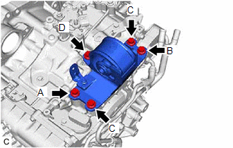
13. INSTALL ENGINE MOUNTING INSULATOR LH
| (a) Install the engine mounting insulator LH to the automatic transaxle case sub-assembly with the 5 bolts. Torque: 42 N·m {428 kgf·cm, 31 ft·lbf} HINT: Tightening order: Temporarily tighten bolt (A) → Fully tighten bolt (B) → Fully tighten bolt (C) → Fully tighten bolt (A) → Fully tighten bolt (D) |
|
14. INSTALL AUTOMATIC TRANSAXLE ASSEMBLY
(a) Apply clutch spline grease to the surface of the crankshaft that contacts the torque converter assembly centerpiece.
Clutch Spline Grease:
Toyota Genuine Clutch Spline Grease or equivalent
Maximum Grease Amount:
Approximately 1 g (0.0353 oz)
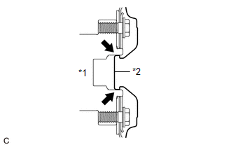
| *1 | Crankshaft |
| *2 | Torque Converter Assembly Centerpiece |
| | Clutch Spline Grease |
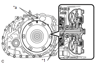
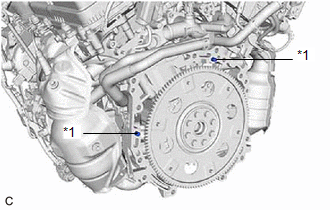
| (b) Confirm that the 2 knock pins are installed on the engine assembly and are not damaged. |
|
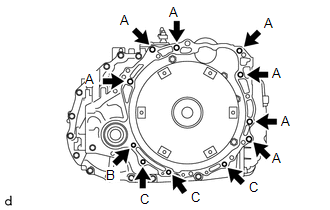
| (c) While keeping the engine assembly and automatic transaxle assembly horizontal, align the knock pins with the holes in the automatic transaxle assembly and install the automatic transaxle assembly with the 11 bolts shown in the illustration. Torque: Bolt (A) : 64 N·m {653 kgf·cm, 47 ft·lbf} Bolt (B) : 46 N·m {469 kgf·cm, 34 ft·lbf} Bolt (C) : 43 N·m {438 kgf·cm, 32 ft·lbf} Bolt Length:
NOTICE:
|
|
15. INSTALL FRONT ENGINE MOUNTING BRACKET
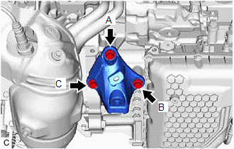
| (a) Install the front engine mounting bracket to the transaxle housing with the 3 bolts. Torque: 42 N·m {428 kgf·cm, 31 ft·lbf} HINT: Tightening order: Temporarily tighten bolt (A) → Fully tighten bolt (B) → Fully tighten bolt (C) → Fully tighten bolt (A) |
|
16. INSTALL FRONT FRAME ASSEMBLY
Click here
17. REMOVE ENGINE HANGERS
Click here
18. CONNECT WIRE HARNESS
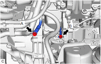
(a) Engage the 3 wire harness clamps to connect the wire harness to the automatic transaxle assembly.
(b) Connect the wire harness to the rack and pinion power steering gear assembly with the 2 bolts.
.png)
Torque:
10 N·m {102 kgf·cm, 7 ft·lbf}
(c) Connect the rack and pinion power steering gear assembly connector.
NOTICE:
Make sure that the connector is fully inserted before rotating the lock lever to engage the lock.
| (d) Install the 2 bolts. Torque: Bolt (A) : 12.5 N·m {127 kgf·cm, 9 ft·lbf} Bolt (B) : 10 N·m {102 kgf·cm, 7 ft·lbf} |
|
(e) Engage the 2 wire harness clamps to connect the wire harness.
(f) Install the bolt.
Torque:
10 N·m {102 kgf·cm, 7 ft·lbf}
(g) Install the 2 bolts.
Torque:
10 N·m {102 kgf·cm, 7 ft·lbf}
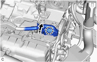
(h) Engage the wire harness clamp and connect the vacuum switching valve (for active control engine mount system) connector.
(i) Connect the park/neutral position switch assembly connector.
| (j) Connect the transmission wire connector and rotate the lever and engage the claw. HINT: Rotate the lever until the claw of the transmission wire connector makes a click sound. |
|
19. CONNECT WATER BY-PASS HOSE ASSEMBLY
(a) Engage the clamp to connect the water by-pass hose assembly to the automatic transaxle assembly.
(b) Connect the water by-pass hose assembly to the transmission oil cooler and slide the clip to secure it.
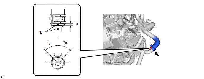
| *a | 2 to 7 mm (0.0787 to 0.276 in.) | *b | Paint Mark |
| *c | 45° (Claw of Clip Location) | - | - |
NOTICE:
- Make sure to slide the water by-pass hose assembly until it contacts the hose stopper of the transmission oil cooler.
- Make sure to align the paint mark of the water by-pass hose assembly with the paint mark of the transmission oil cooler.
- Make sure that the claws of the clip are within the location shown in the illustration.
20. CONNECT NO. 1 WATER BY-PASS HOSE
(a) Connect the No. 1 water by-pass hose to the transmission oil cooler and slide the clip to secure it.
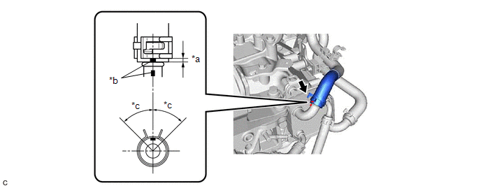
| *a | 2 to 7 mm (0.0787 to 0.276 in.) | *b | Paint Mark |
| *c | 45° (Claw of Clip Location) | - | - |
NOTICE:
- Make sure to slide the No. 1 water by-pass hose until it contacts the hose stopper of the transmission oil cooler.
- Make sure to align the paint mark of the No. 1 water by-pass hose with the paint mark of the transmission oil cooler.
- Make sure that the claws of the clip are within the area shown in the illustration.
(b) Engage the 2 clamps to install the transmission breather clamp.
21. INSTALL BREATHER PLUG HOSE
(a) Install the breather plug sub-assembly to the breather plug hose.
(b) Install the breather plug hose to the No. 1 breather plug (ATM).
(c) Engage the 3 hose clamps to connect the breather plug hose.
22. INSTALL STARTER ASSEMBLY
Click here
23. CONNECT VACUUM HOSE
(a) Engage the 9 clamps to connect the vacuum hose to the automatic transaxle assembly.
(b) Engage the clamp to connect the vacuum hose to the hose clamp.
(c) Connect the vacuum hose to the intake air surge tank assembly.
(d) Connect the vacuum hose to the rear engine mounting insulator.
24. INSTALL ENGINE ASSEMBLY WITH TRANSAXLE
Click here
25. INSTALL DRIVE PLATE AND TORQUE CONVERTER ASSEMBLY SETTING BOLT
(a) Remove any remaining adhesive from the 6 drive plate and torque converter assembly setting bolts.
| (b) Apply a few drops of adhesive to 2 or 3 threads at the tip of each of the 6 drive plate and torque converter assembly setting bolts. Adhesive: Toyota Genuine Adhesive 1324, Three Bond 1324 or equivalent NOTICE: Make sure to install the 6 drive plate and torque converter assembly setting bolts immediately after applying adhesive to prevent foreign matter from attaching to them. |
|
(c) Turn the crankshaft to gain access to the installation locations of the 6 drive plate and torque converter assembly setting bolts and install each drive plate and torque converter assembly setting bolt while holding the crankshaft pulley bolt with a wrench.
Torque:
41 N·m {418 kgf·cm, 30 ft·lbf}
NOTICE:
First install the black colored drive plate and torque converter assembly setting bolt, and then the remaining 5 silver colored drive plate and torque converter assembly setting bolts.
26. INSTALL FLYWHEEL HOUSING UNDER COVER
Click here
27. CHECK AUTOMATIC TRANSAXLE SYSTEM
NOTICE:
If automatic transaxle parts have been replaced, refer to Parts Replacement Compensation Table to determine if any additional operations are necessary.
Click here
READ NEXT:
 Removal
REMOVAL CAUTION / NOTICE / HINT The necessary procedures (adjustment, calibration, initialization, or registration) that must be performed after parts are removed and installed, or replaced during aut
Adjustment
ADJUSTMENT CAUTION / NOTICE / HINT The necessary procedures (adjustment, calibration, initialization or registration) that must be performed after parts are removed and installed, or replaced during a
SEE MORE:
AUTO Power Retract Mirrors do not operate
DESCRIPTION The outer mirror switch assembly sends the retractable outer mirror switch signal to the main body ECU (multiplex network body ECU). The main body ECU (multiplex network body ECU) sends the auto retract/return signal to the outer mirror control ECU assemblies via CAN communication, which
Data List / Active Test
DATA LIST / ACTIVE TEST ACTIVE TEST HINT: Using the Techstream to perform Active Tests allows relays, VSVs, actuators and other items to be operated without removing any parts. This non-intrusive functional inspection can be very useful because intermittent operation may be discovered before parts o
