Lexus ES: Inspection
INSPECTION
PROCEDURE
1. INSPECT SHIFT LOCK CONTROL ECU
HINT:
If the results of the following inspections are as specified but a malfunction has occurred, replace the shift lock control unit assembly.
(a) Inspect wire harness:
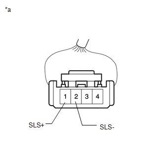
| (1) Disconnect the shift lock control ECU connector. |
|
.png)
| (2) Measure the voltage according to the value(s) in the table below. Standard Voltage:
If the result is not as specified, repair or replace the shift lock control ECU wire harness. |
|
.png)
| (3) Measure the resistance according to the value(s) in the table below. Standard Voltage:
If the result is not as specified, repair or replace the shift lock control ECU wire harness. |
|
.png)
| (4) Measure the resistance according to the value(s) in the table below. Standard Resistance:
If the result is not as specified, repair or replace the shift lock control ECU wire harness. |
|
.png)
(b) Inspect shift lock solenoid:
| (1) Disconnect the shift lock solenoid connector. |
|
.png)
| (2) Measure the resistance according to the value(s) in the table below. Standard Resistance:
If the result is not as specified, replace the shift lock control unit assembly. |
|
.png)
| (3) Measure the resistance according to the value(s) in the table below. Standard Resistance:
If the result is not as specified, replace the shift lock control unit assembly. |
|
2. INSPECT TRANSMISSION CONTROL SWITCH
| (a) Disconnect the transmission control switch connector. |
|
.png)
| (b) Measure the resistance according to the value(s) in the table below. Standard Resistance:
If the result is not as specified, replace the shift lock control unit assembly. |
|
.png)
READ NEXT:
 Installation
INSTALLATION PROCEDURE 1. INSTALL TRANSMISSION FLOOR SHIFT ASSEMBLY (a) Engage the clamp to connect the wire harness to the transmission floor shift assembly. (b) Connect the shift lock control ECU co
On-vehicle Inspection
ON-VEHICLE INSPECTION PROCEDURE 1. SECURE VEHICLE (a) Fully apply the parking brake and chock a wheel. CAUTION:
Make sure to apply the parking brake and chock a wheel before performing this procedu
Reassembly
REASSEMBLY PROCEDURE 1. INSTALL LOWER POSITION INDICATOR HOUSING (a) Engage the 4 claws and 2 guides to install the lower position indicator housing to the shift lock control unit assembly. NOTICE:
SEE MORE:
Satellite Radio Broadcast cannot be Selected or After Selecting Broadcast, Broadcast cannot be Added into Memory
CAUTION / NOTICE / HINT NOTICE: Some satellite radio broadcasts require payment. A contract must be made between a satellite radio company and the user. If the contract expires, it will not be possible to listen to the broadcast. PROCEDURE 1. CHECK SATELLITE RADIO (a) Check radio condition.
Removal
REMOVAL PROCEDURE 1. PRECAUTION (for HV Model) NOTICE:
When replacing the radio receiver assembly or navigation ECU, always replace it with a new one. If a radio receiver assembly or navigation ECU which was installed to another vehicle is used, the following may occur:
A communication malfunc
