Lexus ES: Illumination for Panel Switch does not Come on with Tail Switch ON
Lexus ES (XZ10) Service Manual / Audio & Visual & Telematics / Audio / Video / Audio And Visual System (for Gasoline Model) / Illumination for Panel Switch does not Come on with Tail Switch ON
CAUTION / NOTICE / HINT
NOTICE:
-
Depending on the parts that are replaced during vehicle inspection or maintenance, performing initialization, registration or calibration may be needed. Refer to Precaution for Audio and Visual System.
Click here
.gif)
-
When replacing the radio receiver assembly, always replace it with a new one. If a radio receiver assembly which was installed to another vehicle is used, the following may occur:
- A communication malfunction DTC may be stored.
- The radio receiver assembly may not operate normally.
PROCEDURE
| 1. | CHECK VEHICLE SIGNAL (OPERATION CHECK) |
| (a) Enter the "Vehicle Signal Check Mode" screen. Refer to Check Vehicle Signal in Operation Check. Click here |
|
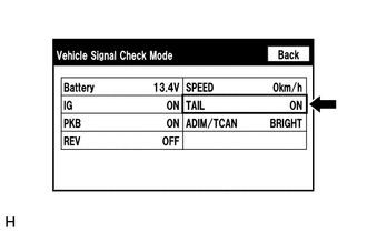
(b) Check that the display changes between ON and OFF according to the light control switch operation.
OK:
| Light Control Switch | Display |
|---|---|
| Tail or head | ON |
| Off or AUTO | OFF |
HINT:
- This display is updated once per second. As a result, it is normal for the display to lag behind the actual switch operation.
- Make sure to move the vehicle to a bright area before performing an operation check with the light control switch in the AUTO position.
| OK |  | REPLACE RADIO RECEIVER ASSEMBLY |
| NG | | PROCEED TO NEXT SUSPECTED AREA SHOWN IN PROBLEM SYMPTOMS TABLE |
READ NEXT:
 Microphone Circuit
DESCRIPTION
The radio receiver assembly and telephone microphone assembly are connected to each other using the microphone connection detection signal lines.
Using this circuit, the radio receive
Mute Signal Circuit between Radio Receiver and Stereo Component Amplifier
DESCRIPTION This circuit sends a signal to the stereo component amplifier assembly to mute noise. Due to this, the noise produced by changing the sound source ceases. If there is an open in the circui
Mute Signal Circuit between Stereo Component Amplifier and Telematics Transceiver
DESCRIPTION The DCM (telematics transceiver) sends a mute signal to the stereo component amplifier assembly. The stereo component amplifier assembly controls the volume according to the mute signal fr
SEE MORE:
Components
COMPONENTS ILLUSTRATION *1 ENGINE OIL LEVEL SENSOR *2 NO. 2 OIL PAN SUB-ASSEMBLY *3 OIL STRAINER SUB-ASSEMBLY *4 OIL STRAINER GASKET N*m (kgf*cm, ft.*lbf): Specified torque ● Non-reusable part
Left Rear Wheel Speed Sensor Circuit Short to Battery (C050C12)
DESCRIPTION Each speed sensor detects wheel speed and sends signals to the skid control ECU (brake actuator assembly). These signals are used by the ABS control. The speed sensor detects the magnetic fields of the speed sensor rotor as it rotates and outputs a pulse signal. The frequency of the puls
© 2016-2026 Copyright www.lexguide.net
