Lexus ES: Front Sensor Communication Malfunction (C1AEC)
DESCRIPTION
This DTC is stored when there is an open or short circuit in the communication line between the front sensors and the ECU, or when there is a malfunction in a front sensor.
| DTC No. | Detection Item | DTC Detection Condition | Trouble Area |
|---|---|---|---|
| C1AEC | Front Sensor Communication Malfunction | An open or short circuit in the communication line between the front sensors and ECU or a malfunction in a front sensor during initialization mode after the power switch is turned on (IG). |
|
WIRING DIAGRAM
.png)
PROCEDURE
| 1. | INITIALIZE FRONT CENTER ULTRASONIC SENSOR AND FRONT CORNER ULTRASONIC SENSOR |
(a) Initialize the front center ultrasonic sensor and front corner ultrasonic sensor.
-
w/o Parking Support Brake System: Click here
.gif)
-
w/ Parking Support Brake System: Click here
|
.gif)
| 2. | CHECK DTC OUTPUT (C1AEC) |
(a) Check for DTCs.
Body Electrical > Advanced Parking Guidance/ICS/Intuitive P/A > Trouble Codes(b) Clear the DTCs.
Body Electrical > Advanced Parking Guidance/ICS/Intuitive P/A > Clear DTCs(c) Recheck for DTCs.
Body Electrical > Advanced Parking Guidance/ICS/Intuitive P/A > Trouble Codes| Result | Proceed to |
|---|---|
| DTC C1AEC is output | A |
| No DTCs are output | B |
| B |  | USE SIMULATION METHOD TO CHECK |
|
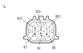
| 3. | CHECK HARNESS AND CONNECTOR (CLEARANCE WARNING ECU ASSEMBLY - FRONT CORNER ULTRASONIC SENSOR RH) |
(a) Disconnect the N41 clearance warning ECU assembly connector.
(b) Disconnect the B1 front corner ultrasonic sensor RH.
(c) Measure the resistance according to the value(s) in the table below.
Standard Resistance:
| Tester Connection | Condition | Specified Condition |
|---|---|---|
| N41-4 (BOF) - B1-4 (BI) | Always | Below 1 Ω |
| N41-8 (SOF) - B1-5 (SI) | Always | Below 1 Ω |
| N41-6 (E5) - B1-6 (EI) | Always | Below 1 Ω |
| N41-4 (BOF) or B1-4 (BI) - Body ground | Always | 10 kΩ or higher |
| N41-8 (SOF) or B1-5 (SI) - Body ground | Always | 10 kΩ or higher |
| N41-6 (E5) or B1-6 (EI) - Body ground | Always | 10 kΩ or higher |
| NG | | REPAIR OR REPLACE HARNESS OR CONNECTOR |
|
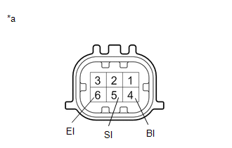
| 4. | CHECK HARNESS AND CONNECTOR (FRONT CORNER ULTRASONIC SENSOR RH - FRONT CENTER ULTRASONIC SENSOR RH) |
(a) Disconnect the B2 front center ultrasonic sensor RH.
(b) Measure the resistance according to the value(s) in the table below.
Standard Resistance:
| Tester Connection | Condition | Specified Condition |
|---|---|---|
| B1-1 (BO) - B2-4 (BI) | Always | Below 1 Ω |
| B1-2 (SO) - B2-5 (SI) | Always | Below 1 Ω |
| B1-3 (EO) - B2-6 (EI) | Always | Below 1 Ω |
| B1-1 (BO) or B2-4 (BI) - Body ground | Always | 10 kΩ or higher |
| B1-2 (SO) or B2-5 (SI) - Body ground | Always | 10 kΩ or higher |
| B1-3 (EO) or B2-6 (EI) - Body ground | Always | 10 kΩ or higher |
| NG | | REPAIR OR REPLACE HARNESS OR CONNECTOR |
|
| 5. | CHECK HARNESS AND CONNECTOR (FRONT CENTER ULTRASONIC SENSOR RH - FRONT CENTER ULTRASONIC SENSOR LH) |
(a) Disconnect the B3 front center ultrasonic sensor LH.
(b) Measure the resistance according to the value(s) in the table below.
Standard Resistance:
| Tester Connection | Condition | Specified Condition |
|---|---|---|
| B2-1 (BO) - B3-4 (BI) | Always | Below 1 Ω |
| B2-2 (SO) - B3-5 (SI) | Always | Below 1 Ω |
| B2-3 (EO) - B3-6 (EI) | Always | Below 1 Ω |
| B2-1 (BO) or B3-4 (BI) - Body ground | Always | 10 kΩ or higher |
| B2-2 (SO) or B3-5 (SI) - Body ground | Always | 10 kΩ or higher |
| B2-3 (EO) or B3-6 (EI) - Body ground | Always | 10 kΩ or higher |
| NG | | REPAIR OR REPLACE HARNESS OR CONNECTOR |
|
| 6. | CHECK HARNESS AND CONNECTOR (FRONT CENTER ULTRASONIC SENSOR LH - FRONT CORNER ULTRASONIC SENSOR LH) |
(a) Disconnect the B4 front corner ultrasonic sensor LH.
(b) Measure the resistance according to the value(s) in the table below.
Standard Resistance:
| Tester Connection | Condition | Specified Condition |
|---|---|---|
| B3-1 (BO) - B4-4 (BI) | Always | Below 1 Ω |
| B3-2 (SO) - B4-5 (SI) | Always | Below 1 Ω |
| B3-3 (EO) - B4-6 (EI) | Always | Below 1 Ω |
| B3-1 (BO) or B4-4 (BI) - Body ground | Always | 10 kΩ or higher |
| B3-2 (SO) or B4-5 (SI) - Body ground | Always | 10 kΩ or higher |
| B3-3 (EO) or B4-6 (EI) - Body ground | Always | 10 kΩ or higher |
| NG | | REPAIR OR REPLACE HARNESS OR CONNECTOR |
|
| 7. | INSPECT FRONT CORNER ULTRASONIC SENSOR RH |
| (a) Measure the resistance according to the value(s) in the table below. Standard Resistance:
|
|
| NG | | REPLACE FRONT CORNER ULTRASONIC SENSOR RH |
|
| 8. | INSPECT FRONT CENTER ULTRASONIC SENSOR RH |
| (a) Measure the resistance according to the value(s) in the table below. Standard Resistance:
|
|
| NG | | REPLACE FRONT CENTER ULTRASONIC SENSOR RH |
|
| 9. | INSPECT FRONT CENTER ULTRASONIC SENSOR LH |
| (a) Measure the resistance according to the value(s) in the table below. Standard Resistance:
|
|
| NG | | REPLACE FRONT CENTER ULTRASONIC SENSOR LH |
|
| 10. | INSPECT FRONT CORNER ULTRASONIC SENSOR LH |
| (a) Measure the resistance according to the value(s) in the table below. Standard Resistance:
|
|
| NG | | REPLACE FRONT CORNER ULTRASONIC SENSOR LH |
|
| 11. | REPLACE FRONT CORNER ULTRASONIC SENSOR RH |
Click here
|
| 12. | CHECK DTC OUTPUT (C1AEC) |
(a) Clear the DTCs.
Body Electrical > Advanced Parking Guidance/ICS/Intuitive P/A > Clear DTCs(b) Check for DTCs.
Body Electrical > Advanced Parking Guidance/ICS/Intuitive P/A > Trouble Codes| Result | Proceed to |
|---|---|
| DTC C1AEC is output | A |
| No DTCs are output | B |
| B | | END (FRONT CORNER ULTRASONIC SENSOR RH WAS DEFECTIVE) |
|
| 13. | REPLACE FRONT CENTER ULTRASONIC SENSOR RH |
Click here
|
| 14. | CHECK DTC OUTPUT (C1AEC) |
(a) Clear the DTCs.
Body Electrical > Advanced Parking Guidance/ICS/Intuitive P/A > Clear DTCs(b) Check for DTCs.
Body Electrical > Advanced Parking Guidance/ICS/Intuitive P/A > Trouble Codes| Result | Proceed to |
|---|---|
| DTC C1AEC is output | A |
| No DTCs are output | B |
| B | | END (FRONT CENTER ULTRASONIC SENSOR RH WAS DEFECTIVE) |
|
| 15. | REPLACE FRONT CENTER ULTRASONIC SENSOR LH |
Click here
|
| 16. | CHECK DTC OUTPUT (C1AEC) |
(a) Clear the DTCs.
Body Electrical > Advanced Parking Guidance/ICS/Intuitive P/A > Clear DTCs(b) Check for DTCs.
Body Electrical > Advanced Parking Guidance/ICS/Intuitive P/A > Trouble Codes| Result | Proceed to |
|---|---|
| DTC C1AEC is output | A |
| No DTCs are output | B |
| B | | END (FRONT CENTER ULTRASONIC SENSOR LH WAS DEFECTIVE) |
|
| 17. | REPLACE FRONT CORNER ULTRASONIC SENSOR LH |
Click here
|
| 18. | CHECK DTC OUTPUT (C1AEC) |
(a) Clear the DTCs.
Body Electrical > Advanced Parking Guidance/ICS/Intuitive P/A > Clear DTCs(b) Check for DTCs.
Body Electrical > Advanced Parking Guidance/ICS/Intuitive P/A > Trouble Codes| Result | Proceed to |
|---|---|
| DTC C1AEC is output | A |
| No DTCs are output | B |
| A | | REPLACE CLEARANCE WARNING ECU ASSEMBLY |
| B | | END (FRONT CORNER ULTRASONIC SENSOR LH WAS DEFECTIVE) |
READ NEXT:
 Rear Sensor Communication Malfunction (C1AED)
DESCRIPTION This DTC is stored when there is an open or short circuit in the communication line between the rear sensors and the ECU, or when there is a malfunction in a rear sensor. DTC No. Dete
Fr Sensor Initialization Incomplete (C1AF3)
DESCRIPTION When it is judged that the front sensors have not been initialized, the clearance warning ECU assembly stores DTC C1AF3. DTC No. Detection Item DTC Detection Condition Trouble Are
Rr Sensor Initialization Incomplete (C1AF4)
DESCRIPTION When it is judged that the rear sensors have not been initialized, the clearance warning ECU assembly stores DTC C1AF4. DTC No. Detection Item DTC Detection Condition Trouble Area
SEE MORE:
DC/DC Converter Temperature Sensor "A" Circuit Voltage Out of Range (P0C381C)
DTC SUMMARY MALFUNCTION DESCRIPTION These DTCs indicate that the boost converter temperature sensor (upper) value is abnormal. The cause of this malfunction may be one of the following: Internal inverter malfunction
Inverter with converter assembly internal circuit malfunction
Hybrid cooling
Blind Spot Monitor Slave Module (C1AB7)
DESCRIPTION This DTC is stored when the blind spot monitor sensor LH detects an internal malfunction. DTC No. Detection Item DTC Detection Condition Trouble Area C1AB7 Blind Spot Monitor Slave Module The blind spot monitor sensor LH (slave) detects an internal malfunction Blind sp
