Lexus ES: Front Recognition Camera Heater Malfunction (C1AAE00)
DESCRIPTION
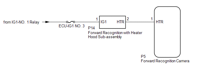
The forward recognition camera controls the flow of current to the forward recognition with heater hood sub-assembly.
If the forward recognition camera detects a malfunction in the forward recognition with heater hood sub-assembly circuit, it will store this DTC.
| DTC No. | Detection Item | DTC Detection Condition | Trouble Area |
|---|---|---|---|
| C1AAE00 | Front Recognition Camera Heater Malfunction | Either of the following conditions is met after 10 seconds have elapsed since the power switch was turned to on (IG):
|
|
WIRING DIAGRAM
CAUTION / NOTICE / HINT
NOTICE:
- Inspect the fuses for circuits related to this system before performing the following procedure.
- When replacing the forward recognition camera, always replace it with a new one. If a forward recognition camera which was installed to another vehicle is used, the information stored in the forward recognition camera will not match the information from the vehicle. As a result, a DTC may be stored.
-
If the forward recognition camera has been replaced with a new one, be sure to perform forward recognition camera adjustment.
HINT:
Forward recognition camera adjustment can be performed by using either One Time Recognition or Sequential Recognition.
One Time Recognition: Click here
.gif)
Sequential Recognition: Click here
PROCEDURE
| 1. | CHECK FOR DTCs |
(a) Clear the DTCs.
Chassis > Front Recognition Camera > Clear DTCs(b) Make sure that the DTC detection conditions are met.
HINT:
If the detection conditions are not met, the system cannot detect the malfunction.
(c) Check for DTCs.
Chassis > Front Recognition Camera > Trouble Codes| Result | Proceed to |
|---|---|
| DTC C1AAE00 is not output | A |
| DTC C1AAE00 is output | B |
| A | .gif) | USE SIMULATION METHOD TO CHECK |
|
.gif)
| 2. | INSPECT FORWARD RECOGNITION WITH HEATER HOOD SUB-ASSEMBLY |
(a) Turn the power switch off.
| (b) Disconnect the forward recognition with heater hood sub-assembly connector. |
|
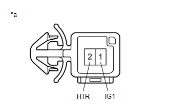
(c) Measure the resistance according to the value(s) in the table below.
Standard Resistance:
| Tester Connection | Condition | Specified Condition |
|---|---|---|
| 1 (IG1) - 2 (HTR) | Power switch off | 28.5 to 31.5 Ω |
(d) Connect the forward recognition with heater hood sub-assembly connector.
| NG | | REPLACE FORWARD RECOGNITION WITH HEATER HOOD SUB-ASSEMBLY |
|
| 3. | CHECK HARNESS AND CONNECTOR (POWER SOURCE VOLTAGE) |
| (a) Disconnect the P14 forward recognition with heater hood sub-assembly connector. |
|
.png)
(b) Measure the voltage according to the value(s) in the table below.
Standard Voltage:
| Tester Connection | Condition | Specified Condition |
|---|---|---|
| P14-1 (IG1) - Body ground | Power switch on (IG) | 8 to 16 V |
| Power switch off | Below 1.5 V |
(c) Connect the P14 forward recognition with heater hood sub-assembly connector.
| NG | | REPAIR OR REPLACE HARNESS OR CONNECTOR (POWER SOURCE CIRCUIT) |
|
| 4. | CHECK HARNESS AND CONNECTOR (FORWARD RECOGNITION WITH HEATER HOOD SUB-ASSEMBLY - FORWARD RECOGNITION CAMERA) |
(a) Disconnect the P14 forward recognition with heater hood sub-assembly connector.
(b) Disconnect the P5 forward recognition camera connector.
(c) Measure the resistance according to the value(s) in the table below.
Standard Resistance:
| Tester Connection | Condition | Specified Condition |
|---|---|---|
| P14-2 (HTR) - P5-1 (HTR) | Always | Below 1 Ω |
| P14-2 (HTR) or P5-1 (HTR) - Body ground | Always | 10 kΩ or higher |
(d) Connect the P5 forward recognition camera connector.
(e) Connect the P14 forward recognition with heater hood sub-assembly connector.
| OK | | REPLACE FORWARD RECOGNITION CAMERA |
| NG | | REPAIR OR REPLACE HARNESS OR CONNECTOR (FORWARD RECOGNITION WITH HEATER HOOD SUB-ASSEMBLY - FORWARD RECOGNITION CAMERA) |
READ NEXT:
 Lost Communication with Multi-axis Acceleration Sensor Module Missing Message (U012587,U012687,U012987,U014087,U029387)
DESCRIPTION When a malfunction is detected between various ECUs and sensors, these DTCs are stored. DTC No. Detection Item DTC Detection Condition Trouble Area U012587 Lost Communicatio
Internal Control Module Software Incompatibility Not Programmed (U030051)
DESCRIPTION The forward recognition camera receives vehicle information from the hybrid vehicle control ECU via CAN communication. DTC U030051 is stored when the vehicle information from the hybrid ve
Internal Control Module Software Incompatibility Invalid / Incompatible Software Component (U030057)
DESCRIPTION Forward recognition camera receives the vehicle information from the hybrid vehicle control ECU via CAN communication. DTC U030057 is stored when the vehicle information from the hybrid ve
SEE MORE:
Installation
INSTALLATION PROCEDURE 1. INSTALL NAVIGATION ANTENNA BRACKET 2. INSTALL NAVIGATION ANTENNA ASSEMBLY (a) Engage the 6 guides and 2 claws to install the navigation antenna assembly as shown in the illustration. Install in this Direction 3. INSTALL NAVIGATION ANTENNA ASSEMBLY WITH BRACKET (a)
Cylinder 1 Injector "B" Circuit Open (P21CF13,P21D013-P21D413)
DESCRIPTION The D-4S system has two injection systems. One is an in-cylinder direct injection system that directly injects pressurized fuel into the combustion chamber. The other is an intake port injection system. The ECM determines the percentage of direct injection and port injection necessary in
