Lexus ES: Engine Coolant Bypass Valve Circuit Short to Ground (P268111,P268115)
DESCRIPTION
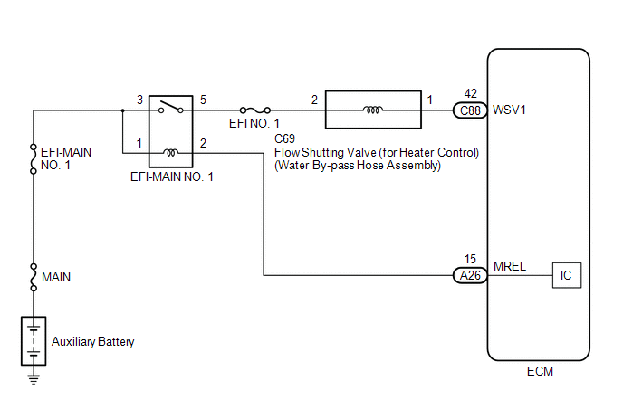
The flow shutting valve (for heater control) used for the variable cooling system is a magnet type valve that is closed when the engine is warming up to prevent coolant from flowing through the heater passage which reduces engine warm up time.
| DTC No. | Detection Item | DTC Detection Condition | Trouble Area | MIL | Memory | Note |
|---|---|---|---|---|---|---|
| P268111 | Engine Coolant Bypass Valve Circuit Short to Ground | All of the following conditions are met (1 trip detection logic).
|
| Does not come on | DTC stored | SAE Code: P2682 |
| P268115 | Engine Coolant Bypass Valve Circuit Short to Battery or Open | All of the following conditions are met (1 trip detection logic).
|
| Does not come on | DTC stored | SAE Code: P2683 |
| DTC No. | Data List |
|---|---|
| P268111 P268115 | Coolant Temperature |
| Coolant Water Route Switching Valve |
MONITOR DESCRIPTION
If the power switch is on (IG) or the engine is running and the current operating state and target operating state of the flow shutting valve (for heater control) do not match, the ECM determines that there is an open or short in the flow shutting valve (for heater control) circuit and stores a DTC.
CONFIRMATION DRIVING PATTERN
HINT:
Make sure to perform this procedure when the engine coolant temperature is between 5 and 40°C (41 and 104°F) and the difference between the engine coolant temperature and intake air temperature is within 10°C (18°F) or less.
- Connect the Techstream to the DLC3.
- Turn the power switch on (IG).
- Turn the Techstream on.
- Clear the DTCs (even if no DTCs are stored, perform the clear DTC procedure).
- Turn the power switch off and wait for at least 30 seconds.
- Turn the power switch on (IG).
- Turn the Techstream on.
- Enter the following menus: Powertrain / Engine / Active Test / Activate the Coolant Water Route Switching Valve.
- Perform the Active Test Activate the Coolant Water Route Switching Valve, select "Close" and wait for 3 seconds or more.
- Perform the Active Test Activate the Coolant Water Route Switching Valve, select "Open" and wait for 3 seconds or more.
- Enter the following menus: Powertrain / Engine / Trouble Codes.
-
Read the pending DTCs.
HINT:
- If a pending DTC is output, the system is malfunctioning.
- If a pending DTC is not output, perform the following procedure.
- Enter the following menus: Powertrain / Engine / Utility / All Readiness.
- Input the DTC: P268111 or P268115.
-
Check the DTC judgment result.
Techstream Display
Description
NORMAL
- DTC judgment completed
- System normal
ABNORMAL
- DTC judgment completed
- System abnormal
INCOMPLETE
- DTC judgment not completed
- Perform driving pattern after confirming DTC enabling conditions
HINT:
- If the judgment result is NORMAL, the system is normal.
- If the judgment result is ABNORMAL, the system is malfunctioning.
- If the judgment result is INCOMPLETE, perform the Confirmation Driving Pattern and check the DTC judgment result again.
WIRING DIAGRAM
CAUTION / NOTICE / HINT
NOTICE:
- Inspect the fuses for circuits related to this system before performing the following procedure.
-
Vehicle Control History may be stored in the hybrid vehicle control ECU assembly if the engine is malfunctioning. Certain vehicle condition information is recorded when Vehicle Control History is stored. Reading the vehicle conditions recorded in both the freeze frame data and Vehicle Control History can be useful for troubleshooting.
Click here
.gif)
(Select Powertrain in Health Check and then check the time stamp data.)
Click here
-
If any "Engine Malfunction" Vehicle Control History item has been stored in the hybrid vehicle control ECU assembly, make sure to clear it. However, as all Vehicle Control History items are cleared simultaneously, if any Vehicle Control History items other than "Engine Malfunction" are stored, make sure to perform any troubleshooting for them before clearing Vehicle Control History.
Click here
HINT:
Read Freeze Frame Data using the Techstream. The ECM records vehicle and driving condition information as Freeze Frame Data the moment a DTC is stored. When troubleshooting, Freeze Frame Data can help determine if the vehicle was moving or stationary, if the engine was warmed up or not, if the air fuel ratio was lean or rich, and other data from the time the malfunction occurred.
PROCEDURE
| 1. | CHECK TERMINAL VOLTAGE (POWER SOURCE OF FLOW SHUTTING VALVE (FOR HEATER CONTROL)) |
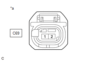
| *a | Front view of wire harness connector (to Water By-pass Hose Assembly) |
(a) Disconnect the water by-pass hose assembly connector.
(b) Turn the power switch on (IG).
(c) Measure the voltage according to the value(s) in the table below.
Standard Voltage:
| Tester Connection | Condition | Specified Condition |
|---|---|---|
| C69-2 - Body ground | Power switch on (IG) | 11 to 14 V |
| NG | .gif) | REPAIR OR REPLACE HARNESS OR CONNECTOR (EFI-MAIN NO. 1 RELAY - FLOW SHUTTING VALVE (FOR HEATER CONTROL)) |
|
.gif)
| 2. | INSPECT WATER BY-PASS HOSE ASSEMBLY |
(a) Inspect the water by-pass hose assembly.
Click here
| NG | | REPLACE FLOW SHUTTING VALVE (FOR HEATER CONTROL) (WATER BY-PASS HOSE ASSEMBLY) |
|
| 3. | CHECK HARNESS AND CONNECTOR (FLOW SHUTTING VALVE (FOR HEATER CONTROL) - ECM) |
(a) Disconnect the water by-pass hose assembly connector.
(b) Disconnect the ECM connector.
(c) Measure the resistance according to the value(s) in the table below.
Standard Resistance:
| Tester Connection | Condition | Specified Condition |
|---|---|---|
| C69-1 - C88-42 (WSV1) | Always | Below 1 Ω |
| C69-1 or C88-42 (WSV1) - Body ground and other terminals | Always | 10 kΩ or higher |
| OK | | REPLACE ECM |
| NG | | REPAIR OR REPLACE HARNESS OR CONNECTOR |
READ NEXT:
 Engine Coolant Pump Circuit Short to Battery (P26CA12)
DESCRIPTION The ECM calculates the necessary cooling amount based on the engine coolant temperature, engine speed and vehicle speed, and controls the water inlet housing with water pump sub-assembly a
Engine Coolant Pump Circuit Short to Ground or Open (P26CA14)
DESCRIPTION Refer to DTC P26CA12. Click here DTC No. Detection Item DTC Detection Condition Trouble Area MIL Memory Note P26CA14 Engine Coolant Pump Circuit Short to Ground or O
Engine Coolant Pump No Signal (P26CA31)
DESCRIPTION Refer to DTC P26CA12. Click here DTC No. Detection Item DTC Detection Condition Trouble Area MIL Memory Note P26CA31 Engine Coolant Pump No Signal The speed of the
SEE MORE:
(Horizontality) G Sensor Malfunction (C1787)
DESCRIPTION The absorber control ECU receives a signal from the yaw rate and acceleration sensor (airbag ECU assembly) via CAN communication. DTC No. Detection Item DTC Detection Condition Trouble Area Warning Indicate Memory C1787 (Horizontality) G Sensor Malfunction While the
Wiper Motor Power Source Circuit
DESCRIPTION This circuit is the power source circuit for the windshield wiper motor assembly. WIRING DIAGRAM CAUTION / NOTICE / HINT NOTICE:
Inspect the fuses of circuits related to this system before performing the following procedure.
Before replacing the main body ECU (multiplex network bod
