Lexus ES: Disassembly
DISASSEMBLY
CAUTION / NOTICE / HINT
The necessary procedures (adjustment, calibration, initialization, or registration) that must be performed after parts are removed and installed, or replaced during rear door removal/installation are shown below.
Necessary Procedure After Parts Removed/Installed/Replaced (for Gasoline Model)| Replaced Part or Performed Procedure | Necessary Procedure | Effect/Inoperative Function When Necessary Procedures are not Performed | Link |
|---|---|---|---|
|
*: When performing learning using the Techstream.
Click here | |||
| Disconnect cable from negative battery terminal | Perform steering sensor zero point calibration | Lane Control System | |
| Pre-collision System | |||
| Parking Support Brake System* | |||
| Lighting System | |||
| Memorize steering angle neutral point | Parking Assist Monitor System | | |
| Panoramic View Monitor System | | ||
| Initialize power trunk lid system | Power Trunk Lid System | | |
| Initialize power window control system |
| |
NOTICE:
- After the engine switch is turned off, the radio receiver assembly records various types of memory and settings. As a result, after turning the engine switch off, make sure to wait at least 85 seconds before disconnecting the cable from the negative (-) battery terminal. (for Audio and Visual System)
- After the engine switch is turned off, the radio receiver assembly records various types of memory and settings. As a result, after turning the engine switch off, make sure to wait at least 85 seconds before disconnecting the cable from the negative (-) battery terminal. (for Navigation System)
| Replaced Part or Performed Procedure | Necessary Procedure | Effect/Inoperative Function When Necessary Procedures are not Performed | Link |
|---|---|---|---|
|
*: When performing learning using the Techstream.
Click here | |||
| Disconnect cable from negative auxiliary battery terminal | Perform steering sensor zero point calibration | Lane Control System | |
| Pre-collision System | |||
| Parking Support Brake System* | |||
| Lighting System | |||
| Memorize steering angle neutral point | Parking Assist Monitor System | | |
| Panoramic View Monitor System | | ||
| Initialize power trunk lid system | Power Trunk Lid System | | |
| Initialize power window control system |
| |
NOTICE:
- After the power switch is turned off, the radio receiver assembly records various types of memory and settings. As a result, after turning the power switch off, make sure to wait at least 85 seconds before disconnecting the cable from the negative (-) auxiliary battery terminal. (for Audio and Visual System)
- After the power switch is turned off, the radio receiver assembly records various types of memory and settings. As a result, after turning the power switch off, make sure to wait at least 85 seconds before disconnecting the cable from the negative (-) auxiliary battery terminal. (for Navigation System)
HINT:
- Use the same procedure for the RH side and LH side.
- The following procedure is for the LH side.
PROCEDURE
1. PRECAUTION
NOTICE:
After turning the engine switch (for Gasoline Model) or power switch (for HV Model) off, waiting time may be required before disconnecting the cable from the negative (-) auxiliary battery terminal. Therefore, make sure to read the disconnecting the cable from the negative (-) auxiliary battery terminal notices before proceeding with work.
2. DISCONNECT CABLE FROM NEGATIVE AUXILIARY BATTERY TERMINAL
for 2GR-FKS:
Click here .gif)
for A25A-FXS:
Click here
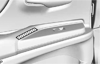
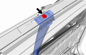
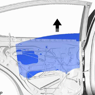
3. REMOVE REAR POWER WINDOW REGULATOR SWITCH ASSEMBLY WITH REAR DOOR UPPER ARMREST BASE PANEL
(a) Apply protective tape to the rear door trim board sub-assembly as shown in the illustration.
.png) | Protective Tape |
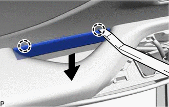
(b) Using a moulding remover, disengage the 2 clips, 4 claws and 3 guides as shown in the illustration.
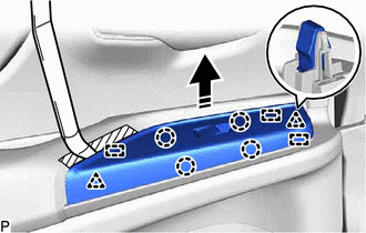
.png) | Remove in this Direction |
(c) Disconnect the connector to remove the rear power window regulator switch assembly with rear door upper armrest base panel.
4. REMOVE REAR DOOR ARMREST COVER
| (a) Remove the rear door armrest cover. |
|
5. REMOVE REAR DOOR TRIM UPPER PAD
| (a) Using a moulding remover, disengage the 2 claws to remove the rear door trim upper pad. |
|
6. REMOVE COURTESY LIGHT ASSEMBLY
Click here
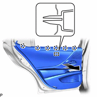
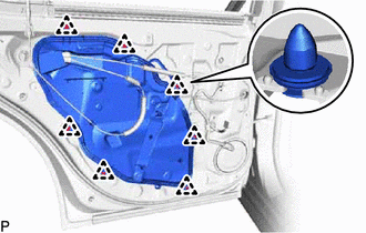
7. REMOVE REAR DOOR TRIM BOARD SUB-ASSEMBLY
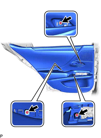
| (a) Using a moulding remover, disengage the 2 claws as shown in the illustration. |
|
| (b) Remove the 3 screws. |
|
(c) Disengage the 8 clips as shown in the illustration.
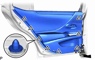
.png) | Place Hand Here |
| | Remove in this Direction |
(d) w/o Rear Door Sunshade:
(1) Disengage the 7 claws and guide as shown in the illustration.
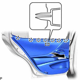
| | Remove in this Direction |
(e) w/ Rear Door Sunshade:
(1) Disengage the 6 claws and guide as shown in the illustration.
| | Remove in this Direction |
(f) w/o Sub Wire Harness:
| (1) Disconnect the connector. |
|
(g) w/ Sub Wire Harness:
| (1) Disconnect the connector. |
|
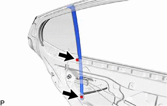
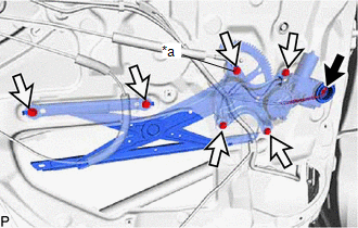
(h) Disconnect the rear door lock open lever remote control cable as shown in the illustration.
| | Remove in this Direction |
(i) Disengage the 2 claws as shown in the illustration to disconnect the rear door inside lock/unlock knob locking cable assembly and remove the rear door trim board sub-assembly.
.png) | Push |
| | Remove in this Direction |
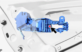
8. REMOVE REAR DOOR INSIDE HANDLE SUB-ASSEMBLY
| (a) Remove the 3 screws and rear door inside handle sub-assembly. |
|
9. REMOVE REAR SPEAKER ASSEMBLY
Click here
10. REMOVE REAR DOOR INSIDE HANDLE ILLUMINATION LIGHT ASSEMBLY (w/ Illumination)
Click here
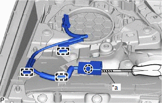
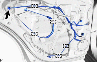
11. REMOVE REAR DOOR WIRE (w/o Illumination)
| (a) w/ Sub Wire Harness: (1) Using a screwdriver with its tip wrapped with protective tape, disengage the claw. (2) Disengage the 3 clamps to remove the rear door wire. |
|
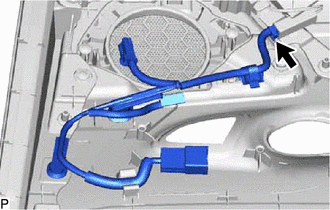
12. REMOVE REAR DOOR WIRE (w/ Illumination)
| (a) Disconnect the connector to remove the rear door wire. |
|
13. REMOVE REAR CURTAIN SUB-ASSEMBLY (w/ Rear Door Sunshade)
| (a) Remove the 6 screws. |
|
(b) Disengage the 3 guides to remove the rear curtain sub-assembly.
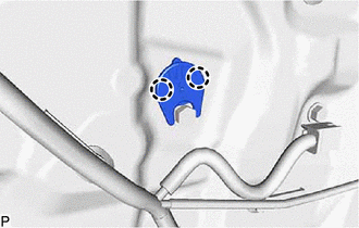
14. REMOVE REAR DOOR DOOR LOCKING HOLDER
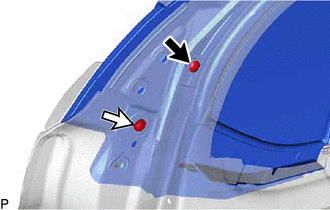
(a) Remove the screw and rear door door locking holder as shown in the illustration.
| | Remove in this Direction |
15. REMOVE REAR DOOR LOCK CONTROL KNOB BEZEL
(a) Remove the rear door lock control knob bezel as shown in the illustration.
| | Remove in this Direction |
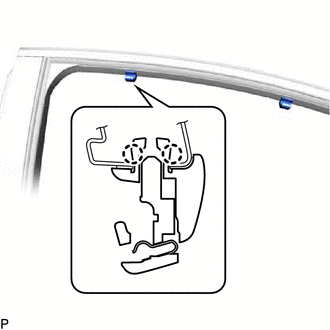
16. REMOVE REAR SIDE CURTAIN ASSEMBLY (w/ Rear Door Sunshade)
(a) Disengage the 2 clips and remove the rear side curtain assembly as shown in the illustration.
| | Remove in this Direction (1) |
.png) | Remove in this Direction (2) |
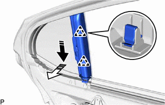
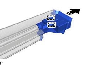
17. REMOVE CURTAIN HOOK (w/ Rear Door Sunshade)
HINT:
Use the same procedure for both curtain hooks.
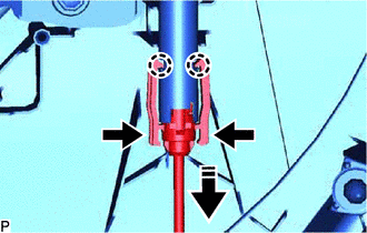
(a) Using a screwdriver with its tip wrapped with protective tape, push out the pin as shown in the illustration.
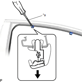
| *a | Protective Tape |
| | Insert Screwdriver Here |
| (b) Disengage the 2 claws to remove the curtain hook. |
|
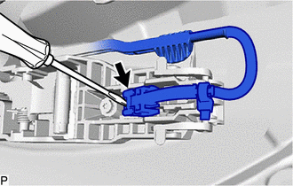
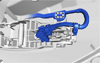
18. REMOVE REAR DOOR SERVICE HOLE COVER
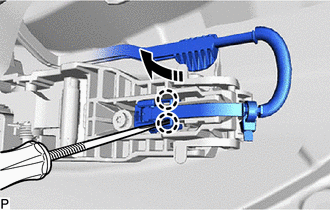
| (a) Disconnect the connector. |
|
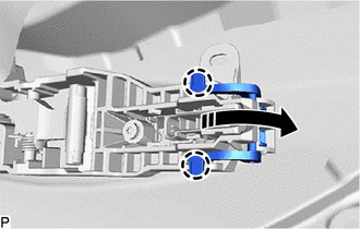
(b) Disengage the 5 clamps.
(c) Remove the 2 screws (A) and screw (B).
| | Screw (A) |
.png) | Screw (B) |
(d) Disengage the guide to remove the bracket.
| (e) Disengage the 7 clips to remove the rear door service hole cover. |
|
19. REMOVE REAR DOOR NO. 1 SERVICE HOLE COVER
| (a) Remove the rear door No. 1 service hole cover. |
|
20. REMOVE REAR DOOR NO. 2 SERVICE HOLE COVER
| (a) Disengage the clip and disconnect the rear door weatherstrip as shown in the illustration. |
|
(b) Remove the rear door inner glass weatherstrip with the rear door No. 2 service hole cover as shown in the illustration.
| | Remove in this Direction |
(c) Disengage the 2 guides to remove the rear door No. 2 service hole cover from the rear door inner glass weatherstrip as shown in the illustration.
| | Remove in this Direction |
21. REMOVE REAR DOOR NO. 2 VENT SEAL
(a) Remove the rear door No. 2 vent seal as shown in the illustration.
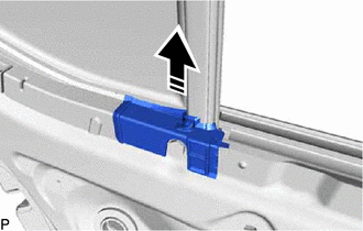
| | Remove in this Direction |
22. REMOVE REAR DOOR PANEL PROTECTOR
| (a) Disengage the clip and disconnect the rear door weatherstrip as shown in the illustration. |
|
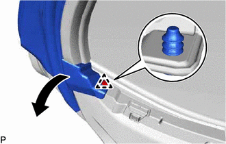
(b) Remove the rear door panel protector as shown in the illustration.
| | Remove in this Direction |
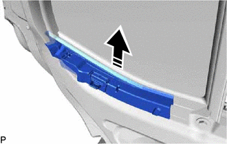
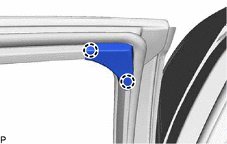
23. REMOVE REAR DOOR FRAME GARNISH
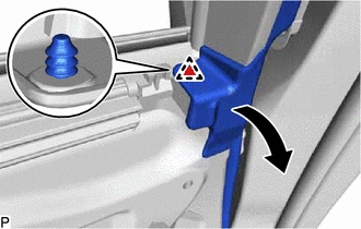
| (a) Disengage the 2 claws to remove the rear door frame garnish. |
|
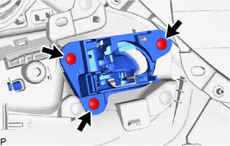
24. REMOVE REAR DOOR CHECK ASSEMBLY
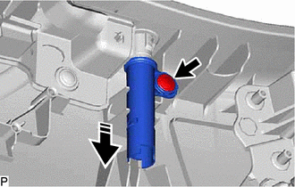
(a) Remove the 2 nuts, bolt and rear door check assembly.
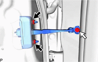
| | Nut |
| | Bolt |
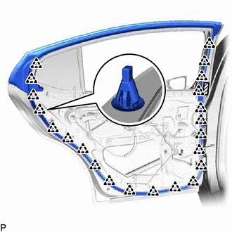
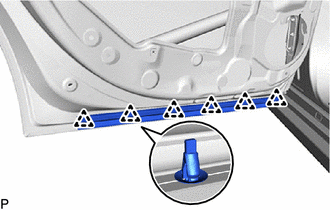
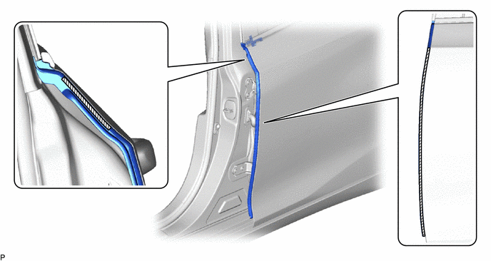
25. REMOVE REAR DOOR WEATHERSTRIP
| (a) Disengage the clip. |
|
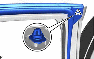
| (b) Disengage the 2 clips. |
|
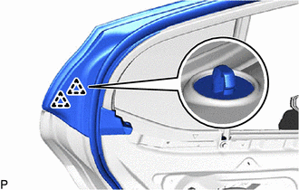
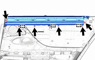
(c) Using a clip remover, disengage the 22 clips and remove the rear door weatherstrip.
| | Double-sided Tape |
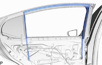
26. REMOVE REAR DOOR GLASS RUN
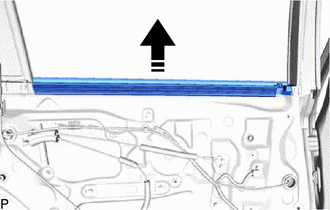
| (a) Remove the rear door glass run. |
|
27. REMOVE REAR DOOR WINDOW DIVISION BAR SUB-ASSEMBLY
| (a) Remove the screw. |
|
| (b) Remove the 2 bolts and rear door window division bar sub-assembly. |
|
28. REMOVE REAR DOOR QUARTER WINDOW GLASS SUB-ASSEMBLY
(a) Remove the screw (A) and screw (B).
| | Screw (A) |
| | Screw (B) |
(b) Remove the rear door quarter window glass sub-assembly as shown in the illustration.
| | Remove in this Direction |
29. REMOVE REAR DOOR GLASS SUB-ASSEMBLY
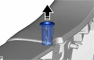
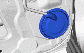
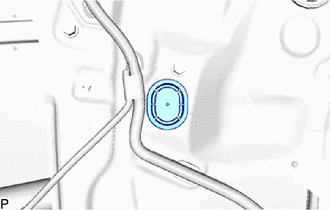
| (a) Remove the hole plug. |
|
(b) Connect the rear power window regulator switch assembly.
(c) Connect the cable to the negative (-) auxiliary battery terminal.
(d) Turn the engine switch (for Gasoline Model) or power switch (for HV Model) on (IG).
(e) Move the rear door glass sub-assembly so that the door glass bolts can be seen.
(f) Turn the engine switch (for Gasoline Model) or power switch (for HV Model) off.
(g) Disconnect the cable from the negative (-) auxiliary battery terminal.
(h) Disconnect the rear power window regulator switch assembly.
| (i) Remove the 2 bolts. NOTICE: After the bolts are removed, do not allow the rear door glass sub-assembly to fall. |
|
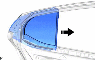
(j) Remove the rear door glass sub-assembly as shown in the illustration.
NOTICE:
Do not damage the rear door glass sub-assembly.
| | Remove in this Direction |
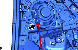
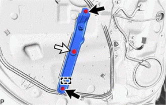
30. REMOVE REAR DOOR WINDOW REGULATOR ASSEMBLY
| (a) Disengage the 2 claws to remove the rear door No. 3 service hole cover. |
|
| (b) Disconnect the connector. |
|
(c) Loosen the temporary bolt.
NOTICE:
Do not remove the temporary bolt. If the temporary bolt is removed, the rear door window regulator assembly may fall and cause damage.
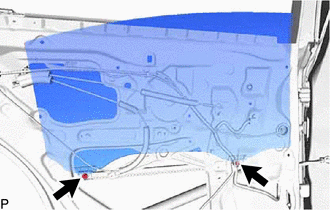
(d) Remove the 5 bolts and rear door window regulator assembly.
(e) Remove the temporary bolt from the rear door window regulator assembly.
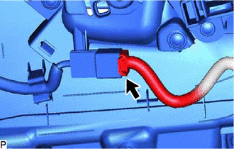
31. REMOVE REAR DOOR LOCK WITH MOTOR ASSEMBLY
Click here
32. REMOVE REAR DOOR LOCK CHILD PROTECTION COVER
| (a) Disengage the 6 claws to remove the rear door lock child protection cover. |
|
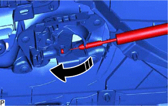
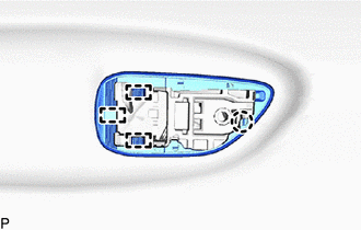
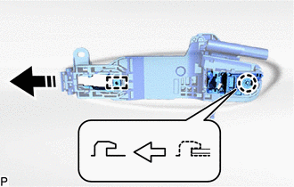
33. REMOVE REAR DOOR OUTSIDE HANDLE ASSEMBLY
(a) Using a screwdriver, disengage the 2 claws as shown in the illustration.
| | Disengage in this Direction |
| (b) Using a screwdriver, disconnect the connector. |
|
| (c) Disengage the clamp. |
|
(d) Disengage the 2 claws and move the lever as shown in the illustration.
| | Disengage in this Direction |
(e) Remove the rear door outside handle assembly as shown in the illustration.
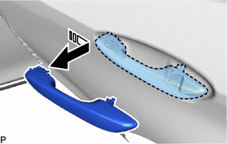
| | Remove in this Direction |
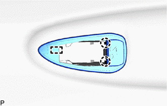
34. REMOVE REAR DOOR OUTSIDE HANDLE COVER
| (a) Using a T30 "TORX" socket wrench, loosen the screw. HINT: The screw cannot be removed because it is integrated into the rear door outside handle frame sub-assembly. |
|
(b) Disengage the 2 claws to remove the rear door outside handle cover.
35. REMOVE REAR DOOR FRONT OUTSIDE HANDLE PAD
| (a) Disengage the 2 claws and guide to remove the rear door front outside handle pad. |
|
36. REMOVE REAR DOOR REAR OUTSIDE HANDLE PAD
| (a) Disengage the claw and 3 guides to remove the rear door rear outside handle pad. |
|
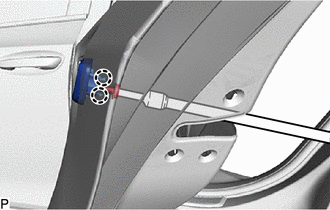
37. REMOVE REAR DOOR OUTSIDE HANDLE FRAME SUB-ASSEMBLY
| (a) Using a T30 "TORX" socket wrench, remove the screw. |
|
(b) Disengage the claw and guide to remove rear door outside handle frame sub-assembly as shown in the illustration.
| | Remove in this Direction |
38. REMOVE REAR DOOR BELT MOULDING ASSEMBLY
Click here
39. REMOVE REAR DOOR BELT MOULDING SUB-ASSEMBLY
Click here
40. REMOVE REAR DOOR FRONT WINDOW FRAME MOULDING
Click here
41. REMOVE REAR DOOR WINDOW FRAME MOULDING SUB-ASSEMBLY
Click here
42. REMOVE FRONT INNER BLACK OUT TAPE
Click here
43. REMOVE UPPER INNER BLACK OUT TAPE
Click here
44. REMOVE REAR INNER BLACK OUT TAPE
Click here
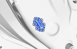
45. REMOVE REAR DOOR NO. 2 WEATHERSTRIP
| (a) Disengage the 6 clips to remove the rear door No. 2 weatherstrip. |
|
46. REMOVE REAR DOOR NO. 3 WEATHERSTRIP
(a) Remove the rear door No. 3 weatherstrip.
| | Double-sided Tape | - | - |
47. REMOVE REAR DOOR PANEL CUSHION
| (a) Disengage the 4 claws to remove the 2 rear door panel cushions. |
|
READ NEXT:
 Adjustment
ADJUSTMENT CAUTION / NOTICE / HINT *a Centering Bolt *b Standard Bolt HINT:
Use the same procedure for the RH side and LH side.
The following procedure is for the LH side.
Center
Reassembly
REASSEMBLY CAUTION / NOTICE / HINT HINT:
Use the same procedure for the RH side and LH side.
The following procedure is for the LH side.
PROCEDURE 1. PRECAUTION NOTICE: After turning the engin
Reassembly
REASSEMBLY CAUTION / NOTICE / HINT HINT:
Use the same procedure for the RH side and LH side.
The following procedure is for the LH side.
PROCEDURE 1. PRECAUTION NOTICE: After turning the engin
SEE MORE:
Lost Communication with Airbag System Control Module Signal Plausibility Failure (P310764)
DESCRIPTION Refer to the description for DTC P310711. Click here DTC No. Detection Item DTC Detection Condition Trouble Area MIL Warning Indicate P310764 Lost Communication with Airbag System Control Module Signal Plausibility Failure Abnormal communication signal: Communicati
Components
COMPONENTS ILLUSTRATION *A for A25A-FXS - - *1 FRONT FRAME ASSEMBLY *2 FUEL DELIVERY GUARD *3 STEERING GEAR HEAT INSULATOR *4 WIRE HARNESS *5 FRONT ENGINE MOUNTING INSULATOR *6 REAR ENGINE MOUNTING INSULATOR Tightening torque for "Major areas involving
