Lexus ES: Components
COMPONENTS
ILLUSTRATION
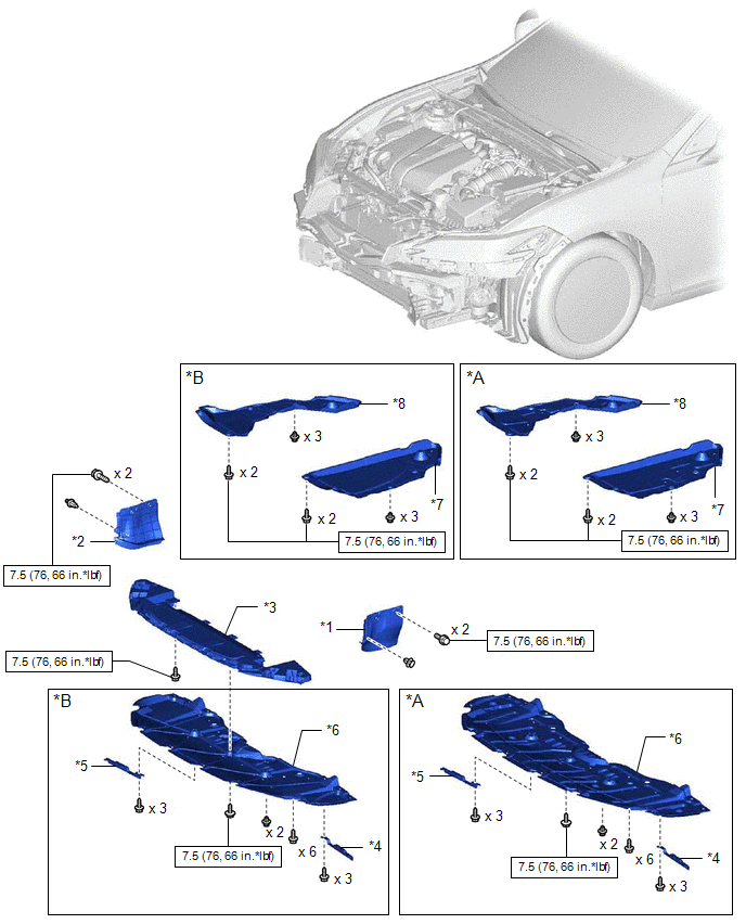
| *A | Type A | *B | Type B |
| *1 | FRONT FENDER APRON SEAL LH | *2 | FRONT FENDER APRON SEAL RH |
| *3 | FRONT LOWER BUMPER ABSORBER | *4 | FRONT WHEEL OPENING EXTENSION PAD LH |
| *5 | FRONT WHEEL OPENING EXTENSION PAD RH | *6 | NO. 1 ENGINE UNDER COVER |
| *7 | NO. 3 ENGINE UNDER COVER | *8 | NO. 2 ENGINE UNDER COVER |
.png) | N*m (kgf*cm, ft.*lbf): Specified torque | - | - |
ILLUSTRATION
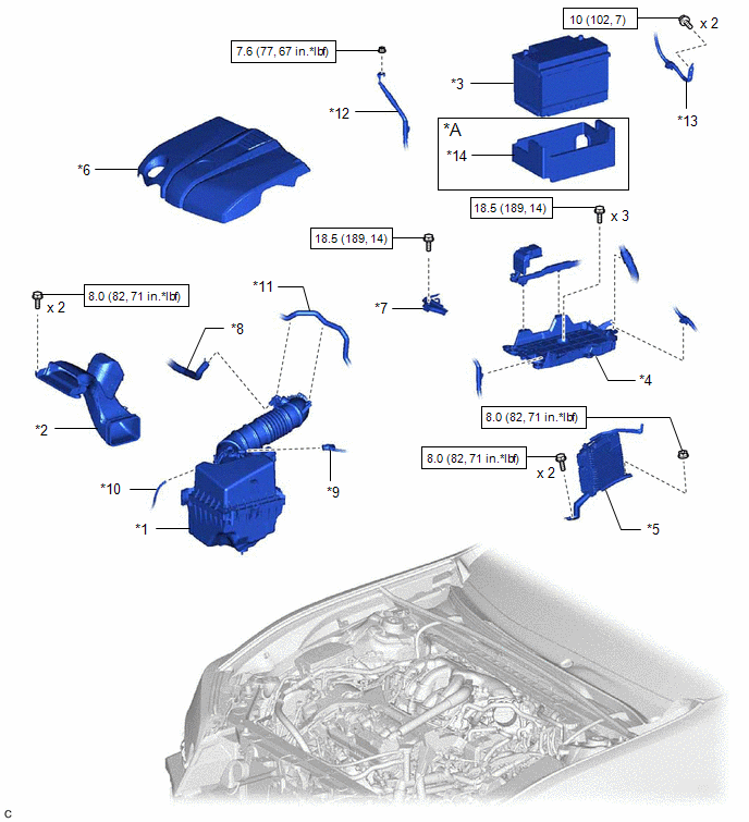
| *A | w/ Battery Insulator | - | - |
| *1 | AIR CLEANER ASSEMBLY WITH AIR CLEANER HOSE | *2 | INLET AIR CLEANER ASSEMBLY |
| *3 | BATTERY | *4 | BATTERY CLAMP SUB-ASSEMBLY |
| *5 | ECM | *6 | V-BANK COVER SUB-ASSEMBLY |
| *7 | NO. 2 BATTERY CLAMP | *8 | NO. 2 VENTILATION HOSE |
| *9 | MASS AIR FLOW METER SUB-ASSEMBLY CONNECTOR | *10 | VACUUM HOSE |
| *11 | NO. 1 FUEL VAPOR FEED HOSE | *12 | ENGINE ROOM MAIN WIRE |
| *13 | EARTH WIRE | *14 | BATTERY INSULATOR |
| | N*m (kgf*cm, ft.*lbf): Specified torque | - | - |
ILLUSTRATION
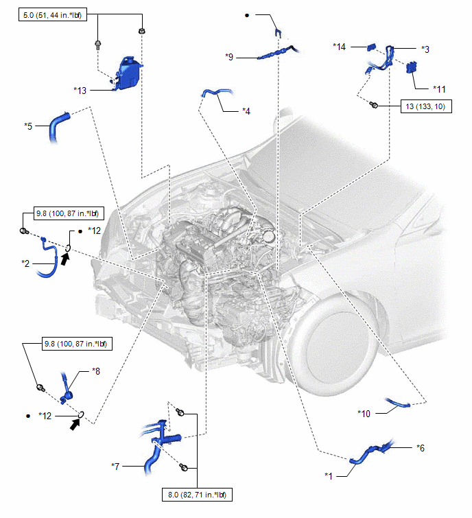
| *1 | INLET HEATER WATER HOSE | *2 | NO. 1 COOLER REFRIGERANT DISCHARGE HOSE |
| *3 | NO. 1 FUEL HOSE | *4 | NO. 1 FUEL VAPOR FEED HOSE |
| *5 | NO. 2 RADIATOR HOSE | *6 | OUTLET HEATER WATER HOSE |
| *7 | RADIATOR HOSE SUB-ASSEMBLY | *8 | SUCTION HOSE |
| *9 | TRANSMISSION CONTROL CABLE ASSEMBLY | *10 | UNION TO CHECK VALVE HOSE |
| *11 | NO. 1 FUEL PIPE CLAMP | *12 | O-RING |
| *13 | RADIATOR RESERVE TANK ASSEMBLY | *14 | NO. 2 FUEL PIPE CLAMP |
| | N*m (kgf*cm, ft.*lbf): Specified torque | ● | Non-reusable part |
.png) | Compressor oil ND-OIL 12 or equivalent | - | - |
ILLUSTRATION
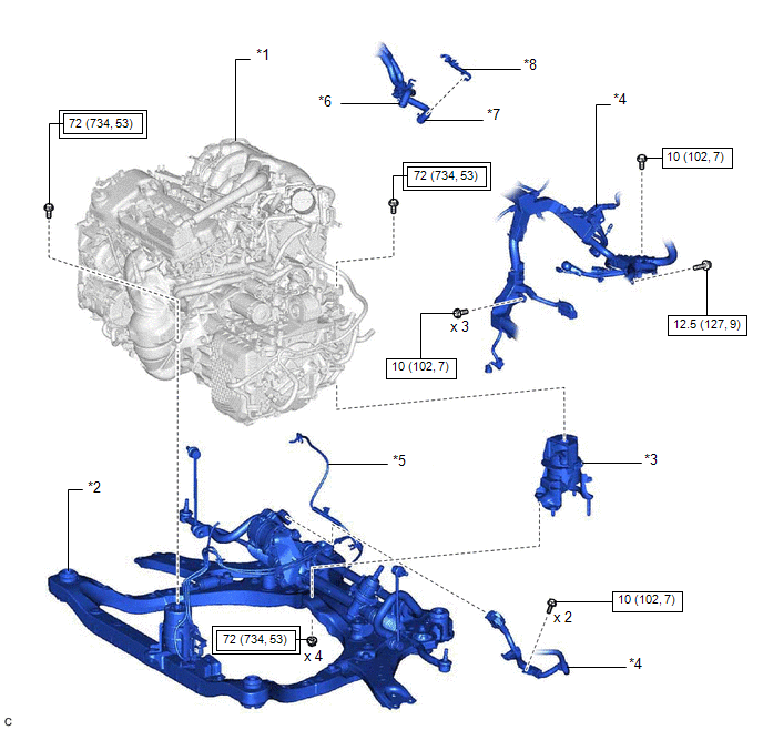
| *1 | ENGINE ASSEMBLY WITH TRANSAXLE | *2 | FRONT FRAME ASSEMBLY |
| *3 | REAR ENGINE MOUNTING INSULATOR | *4 | WIRE HARNESS |
| *5 | VACUUM HOSE | *6 | NO. 1 WATER BY-PASS HOSE |
| *7 | WATER BY-PASS HOSE ASSEMBLY | *8 | TRANSMISSION BREATHER CLAMP |
.png) | Tightening torque for "Major areas involving basic vehicle performance such as moving/turning/stopping": N*m (kgf*cm, ft.*lbf) | | N*m (kgf*cm, ft.*lbf): Specified torque |
ILLUSTRATION
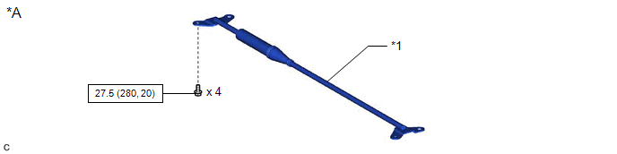
| *A | w/ Suspension Tower Damper | - | - |
| *1 | SUSPENSION TOWER DAMPER | - | - |
| | N*m (kgf*cm, ft.*lbf): Specified torque | - | - |
ILLUSTRATION
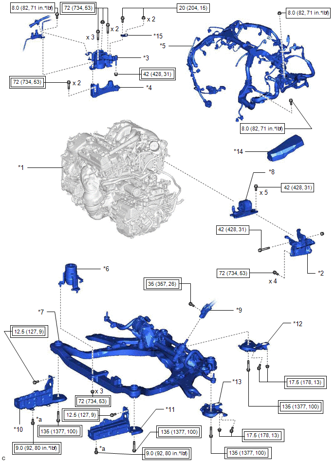
| *1 | ENGINE ASSEMBLY WITH TRANSAXLE | *2 | ENGINE MOUNTING BRACKET SUB-ASSEMBLY LH |
| *3 | ENGINE MOUNTING INSULATOR SUB-ASSEMBLY RH | *4 | ENGINE MOUNTING SPACER |
| *5 | ENGINE WIRE | *6 | FRONT ENGINE MOUNTING INSULATOR |
| *7 | FRONT FRAME ASSEMBLY | *8 | ENGINE MOUNTING INSULATOR LH |
| *9 | STEERING INTERMEDIATE SHAFT ASSEMBLY | *10 | FRONT BUMPER EXTENSION SUB-ASSEMBLY RH |
| *11 | FRONT BUMPER EXTENSION SUB-ASSEMBLY LH | *12 | FRONT SUSPENSION MEMBER BRACKET SUB-ASSEMBLY RH |
| *13 | FRONT SUSPENSION MEMBER BRACKET SUB-ASSEMBLY LH | *14 | NO. 2 RELAY BLOCK COVER |
| *15 | NO. 2 ENGINE MOUNTING STAY RH | - | - |
| *a | w/o Suspension Tower Damper: x 2 w/ Suspension Tower Damper: x 1 | - | - |
| | Tightening torque for "Major areas involving basic vehicle performance such as moving/turning/stopping": N*m (kgf*cm, ft.*lbf) | | N*m (kgf*cm, ft.*lbf): Specified torque |
ILLUSTRATION
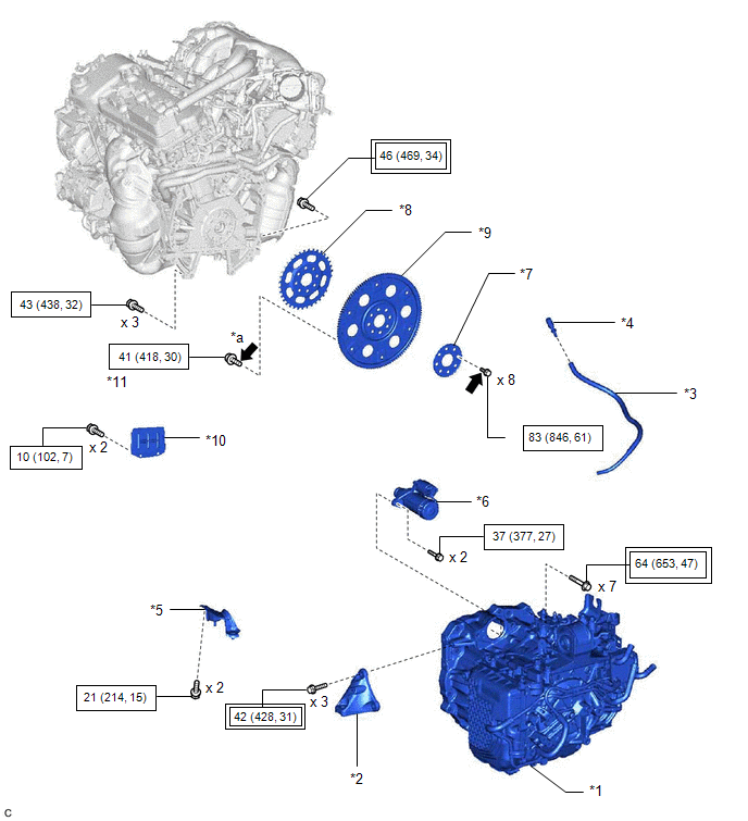
| *1 | AUTOMATIC TRANSAXLE ASSEMBLY | *2 | FRONT ENGINE MOUNTING BRACKET |
| *3 | BREATHER PLUG HOSE | *4 | BREATHER PLUG SUB-ASSEMBLY |
| *5 | NO. 1 EXHAUST PIPE SUPPORT BRACKET (for Upper Side) | *6 | STARTER ASSEMBLY |
| *7 | REAR DRIVE PLATE SPACER | *8 | NO. 1 CRANKSHAFT POSITION SENSOR PLATE |
| *9 | DRIVE PLATE AND RING GEAR SUB-ASSEMBLY | *10 | FLYWHEEL HOUSING UNDER COVER |
| *11 | DRIVE PLATE AND TORQUE CONVERTER ASSEMBLY SETTING BOLT | - | - |
| *a | BLACK COLOR: x 1 SILVER COLOR: x 5 | - | - |
| | Tightening torque for "Major areas involving basic vehicle performance such as moving/turning/stopping": N*m (kgf*cm, ft.*lbf) | | N*m (kgf*cm, ft.*lbf): Specified torque |
| | Adhesive 1324 | ★ | Precoated part |
READ NEXT:
 Removal
REMOVAL CAUTION / NOTICE / HINT The necessary procedures (adjustment, calibration, initialization or registration) that must be performed after parts are removed and installed, or replaced during engi
Installation
INSTALLATION CAUTION / NOTICE / HINT CAUTION:
The engine assembly with transaxle is very heavy. Be sure to follow the procedure described in the repair manual, or the engine lifter may suddenly dro
SEE MORE:
Variation Code not Written (B2451)
DESCRIPTION The headlight ECU sub-assembly LH stores this DTC if the vehicle specifications have not been stored. for LED Type Turn Signal Light DTC No. Detection Item DTC Detection Condition Trouble Area DTC Output from B2451 Variation Code not Written
The power switch is on (
Torque Converter Clutch Circuit Short to Ground (P074011)
DESCRIPTION Solenoid (SL) valve is turned on and off by signals from the ECM to control the hydraulic pressure acting on the lock-up relay valve, which then controls operation of the lock-up clutch. DTC No. Detection Item DTC Detection Condition Trouble Area MIL Memory Note P07401
