Lexus ES: Check Bus 4 Lines for Short Circuit
DESCRIPTION
There may be a short circuit between the CAN main bus lines and/or CAN branch lines when the resistance between terminals 22 (CA2H) and 7 (CA2L) of the central gateway ECU (network gateway ECU) is below 54 Ω.
| Symptom | Trouble Area |
|---|---|
| Resistance between terminals 22 (CA2H) and 7 (CA2L) of the central gateway ECU (network gateway ECU) is below 54 Ω. |
|
WIRING DIAGRAM
.png)
.png)
CAUTION / NOTICE / HINT
CAUTION:
When performing the confirmation driving pattern, obey all speed limits and traffic laws.
NOTICE:
-
Because the order of diagnosis is important to allow correct diagnosis, make sure to begin troubleshooting using How to Proceed with Troubleshooting when CAN communication system related DTCs are output.
Click here
.gif)
- Before measuring the resistance of the CAN bus, turn the engine switch off and leave the vehicle for 1 minute or more without operating the key or any switches, or opening or closing the doors. After that, disconnect the cable from the negative (-) battery terminal and leave the vehicle for 1 minute or more before measuring the resistance.
-
After turning the engine switch off, waiting time may be required before disconnecting the cable from the negative (-) battery terminal. Therefore, make sure to read the disconnecting the cable from the negative (-) battery terminal notices before proceeding with work.
Click here
-
After performing repairs, perform the DTC check procedure and confirm that the DTCs are not output again.
DTC check procedure: Turn the engine switch on (IG) and wait for 1 minute or more. Then operate the suspected malfunctioning system and drive the vehicle at 60 km/h (37 mph) or more for 5 minutes or more.
-
After the repair, perform the CAN bus check and check that all the ECUs and sensors connected to the CAN communication system are displayed as normal.
Click here
HINT:
- Before disconnecting related connectors for inspection, push in on each connector body to check that the connector is not loose or disconnected.
- When a connector is disconnected, check that the terminals and connector body are not cracked, deformed or corroded.
PROCEDURE
| 1. | CHECK FOR SHORT IN CAN BUS LINES (NO. 7 CAN JUNCTION CONNECTOR) |
(a) Disconnect the cable from the negative (-) battery terminal.
(b) Disconnect the N99 No. 7 CAN junction connector.
(c) Measure the resistance according to the value(s) in the table below.
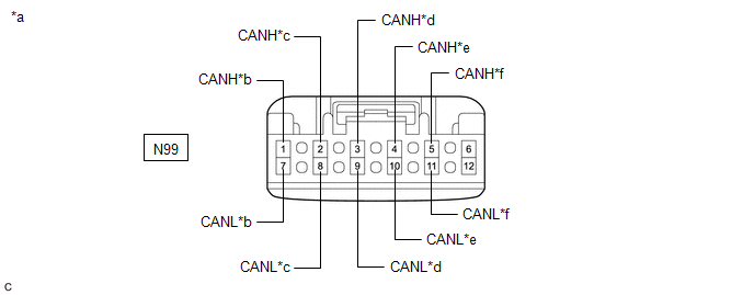
| *a | Front view of wire harness connector (to No. 7 CAN Junction Connector) | *b | to Tire Pressure Warning ECU and Receiver |
| *c | to Occupant Detection ECU | *d | to Central Gateway ECU (Network Gateway ECU) |
| *e | to No. 4 CAN Junction Connector | *f | to Absorber Control ECU (w/ AVS System) |
Standard Resistance:
| Tester Connection | Condition | Specified Condition | Connected to |
|---|---|---|---|
| N99-1 (CANH) - N99-7 (CANL) | Cable disconnected from negative (-) battery terminal | 200 Ω or higher | Tire pressure warning ECU and receiver |
| N99-2 (CANH) - N99-8 (CANL) | Cable disconnected from negative (-) battery terminal | 200 Ω or higher | Occupant detection ECU |
| N99-3 (CANH) - N99-9 (CANL) | Cable disconnected from negative (-) battery terminal | 108 to 132 Ω | Central gateway ECU (network gateway ECU) |
| N99-4 (CANH) - N99-10 (CANL) | Cable disconnected from negative (-) battery terminal | 108 to 132 Ω | No. 4 CAN junction connector |
| N99-5 (CANH) - N99-11 (CANL) | Cable disconnected from negative (-) battery terminal | 200 Ω or higher | Absorber control ECU* |
- *: w/ AVS System
| Result | Proceed to |
|---|---|
| OK | A |
| NG (Line to central gateway ECU (network gateway ECU)) | B |
| NG (Line to No. 4 CAN junction connector) | C |
| NG (Line to ECU or sensor) | D |
| A | .gif) | REPLACE NO. 7 CAN JUNCTION CONNECTOR |
| C | | GO TO STEP 3 |
| D | | GO TO STEP 7 |
|
.gif)
| 2. | CHECK FOR SHORT IN CAN BUS LINES (NO. 7 CAN JUNCTION CONNECTOR - CENTRAL GATEWAY ECU (NETWORK GATEWAY ECU)) |
(a) Disconnect the G66 central gateway ECU (network gateway ECU) connector.
(b) Measure the resistance according to the value(s) in the table below.
.png)
| *a | Front view of wire harness connector (to No. 7 CAN Junction Connector) | *b | to Central Gateway ECU (Network Gateway ECU) |
Standard Resistance:
| Tester Connection | Condition | Specified Condition |
|---|---|---|
| N99-3 (CANH) - N99-9 (CANL) | Cable disconnected from negative (-) battery terminal | 1 MΩ or higher |
| OK | | REPLACE CENTRAL GATEWAY ECU (NETWORK GATEWAY ECU) |
| NG | | REPAIR OR REPLACE CAN MAIN BUS LINES OR CONNECTOR (NO. 7 CAN JUNCTION CONNECTOR - CENTRAL GATEWAY ECU (NETWORK GATEWAY ECU)) |
| 3. | CHECK FOR SHORT IN CAN BUS LINES (NO. 4 CAN JUNCTION CONNECTOR - NO. 7 CAN JUNCTION CONNECTOR) |
(a) Reconnect the N99 No. 7 CAN junction connector.
(b) Disconnect the G99 No. 4 CAN junction connector.
(c) Measure the resistance according to the value(s) in the table below.
.png)
| *a | Front view of wire harness connector (to No. 4 CAN Junction Connector) | *b | to No. 7 CAN Junction Connector |
Standard Resistance:
| Tester Connection | Condition | Specified Condition |
|---|---|---|
| G99-6 (CANH) - G99-17 (CANL) | Cable disconnected from negative (-) battery terminal | 108 to 132 Ω |
| NG | | REPAIR OR REPLACE CAN MAIN BUS LINES OR CONNECTOR (NO. 4 CAN JUNCTION CONNECTOR - NO. 7 CAN JUNCTION CONNECTOR) |
|
| 4. | CHECK FOR SHORT IN CAN BUS LINES (NO. 4 CAN JUNCTION CONNECTOR) |
(a) Reconnect the G99 No. 4 CAN junction connector.
(b) Disconnect the G98 No. 4 CAN junction connector.
(c) Measure the resistance according to the value(s) in the table below.
.png)
| *a | Front view of wire harness connector (to No. 4 CAN Junction Connector) | *b | to No. 2 CAN Junction Connector |
| *c | to Steering Sensor | - | - |
Standard Resistance:
| Tester Connection | Condition | Specified Condition | Connected to |
|---|---|---|---|
| G98-6 (CANH) - G98-17 (CANL) | Cable disconnected from negative (-) battery terminal | 108 to 132 Ω | No. 2 CAN junction connector |
| G98-7 (CANH) - G98-18 (CANL) | Cable disconnected from negative (-) battery terminal | 200 Ω or higher | Steering sensor |
| Result | Proceed to |
|---|---|
| OK | A |
| NG (Line to No. 2 CAN junction connector) | B |
| NG (Line to ECU or sensor) | C |
| A | | REPLACE NO. 4 CAN JUNCTION CONNECTOR |
| C | | GO TO STEP 7 |
|
| 5. | CHECK FOR SHORT IN CAN BUS LINES (NO. 2 CAN JUNCTION CONNECTOR) |
(a) Reconnect the G98 No. 4 CAN junction connector.
(b) Disconnect the A69 No. 2 CAN junction connector.
(c) Measure the resistance according to the value(s) in the table below.
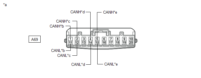
| *a | Front view of wire harness connector (to No. 2 CAN Junction Connector) | *b | to Brake Actuator Assembly |
| *c | to Airbag ECU Assembly | *d | to Rack and Pinion Power Steering Gear Assembly |
| *e | to No. 4 CAN Junction Connector | - | - |
Standard Resistance:
| Tester Connection | Condition | Specified Condition | Connected to |
|---|---|---|---|
| A69-1 (CANH) - A69-11 (CANL) | Cable disconnected from negative (-) battery terminal | 200 Ω or higher | Brake actuator assembly |
| A69-2 (CANH) - A69-12 (CANL) | Cable disconnected from negative (-) battery terminal | 108 to 132 Ω | Airbag ECU assembly |
| A69-4 (CANH) - A69-14 (CANL) | Cable disconnected from negative (-) battery terminal | 200 Ω or higher | Rack and pinion power steering gear assembly |
| A69-5 (CANH) - A69-15 (CANL) | Cable disconnected from negative (-) battery terminal | 108 to 132 Ω | No. 4 CAN junction connector |
| Result | Proceed to |
|---|---|
| OK | A |
| NG (Line to airbag ECU assembly) | B |
| NG (Line to No. 4 CAN junction connector) | C |
| NG (Line to ECU or sensor) | D |
| A | | REPLACE NO. 2 CAN JUNCTION CONNECTOR |
| C | | REPAIR OR REPLACE CAN MAIN BUS LINES OR CONNECTOR (NO. 2 CAN JUNCTION CONNECTOR - NO. 4 CAN JUNCTION CONNECTOR) |
| D | | GO TO STEP 7 |
|
| 6. | CHECK FOR SHORT IN CAN BUS LINES (NO. 2 CAN JUNCTION CONNECTOR - AIRBAG ECU ASSEMBLY) |
(a) Disconnect the G64 airbag ECU assembly connector.
(b) Measure the resistance according to the value(s) in the table below.
.png)
| *a | Front view of wire harness connector (to No. 2 CAN Junction Connector) | *b | to Airbag ECU Assembly |
Standard Resistance:
| Tester Connection | Condition | Specified Condition |
|---|---|---|
| A69-2 (CANH) - A69-12 (CANL) | Cable disconnected from negative (-) battery terminal | 1 MΩ or higher |
| OK | | REPLACE AIRBAG ECU ASSEMBLY |
| NG | | REPAIR OR REPLACE CAN MAIN BUS LINES OR CONNECTOR (NO. 2 CAN JUNCTION CONNECTOR - AIRBAG ECU ASSEMBLY) |
| 7. | CHECK FOR SHORT IN CAN BUS LINES (ECU OR SENSOR) |
(a) Reconnect all wire harness connectors.
(b) Disconnect the connector that includes terminals CANH and CANL from the ECU or sensor to which the short circuited branch line is connected.
Click here
| (c) Measure the resistance according to the value(s) in the table below. Standard Resistance:
HINT:
|
|
.png)
| OK | | REPLACE ECU OR SENSOR |
| NG | | REPAIR OR REPLACE HARNESS OR CONNECTOR |
READ NEXT:
 Open in Bus 4 Main Bus Line
DESCRIPTION There may be an open circuit in one of the CAN main bus lines when the resistance between terminals 22 (CA2H) and 7 (CA2L) of the central gateway ECU (network gateway ECU) is 70 Ω or high
Open in One Side of Bus 3 Branch Line
DESCRIPTION When the CAN bus main lines are normal (no open, short to ground, short to +B or short between lines) and there is an ECU or sensor on the "Communication Bus Check" screen that is indicate
Open in One Side of Bus 3 Branch Line
DESCRIPTION When the CAN bus main lines are normal (no open, short to ground, short to +B or short between lines) and there is an ECU or sensor on the "Communication Bus Check" screen that is indicate
SEE MORE:
How To Proceed With Troubleshooting
CAUTION / NOTICE / HINT HINT:
Use these procedures to troubleshoot the grille shutter system.
*: Use the Techstream.
PROCEDURE 1. VEHICLE BROUGHT TO WORKSHOP
NEXT 2. CUSTOMER PROBLEM ANALYSIS HINT:
In troubleshooting, confirm that the problem symptoms ha
ECU Power Source Circuit System Voltage Low (B2620A2)
DESCRIPTION The ECU power source circuit supplies positive (+) voltage to the multiplex tilt and telescopic ECU. DTC No. Detection Item DTC Detection Condition Trouble Area B2620A2 ECU Power Source Circuit System Voltage Low The voltage of the ECU power source drops to 8 V or less f
