Lexus ES: Bus Buffer ECU Communication Stop Mode
DESCRIPTION
| Detection Item | Symptom | Trouble Area |
|---|---|---|
| Bus Buffer ECU Communication Stop Mode | Any of the following conditions are met:
|
|
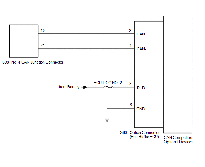
WIRING DIAGRAM
CAUTION / NOTICE / HINT
CAUTION:
When performing the confirmation driving pattern, obey all speed limits and traffic laws.
NOTICE:
-
Because the order of diagnosis is important to allow correct diagnosis, make sure to begin troubleshooting using How to Proceed with Troubleshooting when CAN communication system related DTCs are output.
Click here
.gif)
- Before measuring the resistance of the CAN bus, turn the engine switch off and leave the vehicle for 1 minute or more without operating the key or any switches, or opening or closing the doors. After that, disconnect the cable from the negative (-) battery terminal and leave the vehicle for 1 minute or more before measuring the resistance.
-
After turning the engine switch off, waiting time may be required before disconnecting the cable from the negative (-) battery terminal. Therefore, make sure to read the disconnecting the cable from the negative (-) battery terminal notices before proceeding with work.
Click here
-
After performing repairs, perform the DTC check procedure and confirm that the DTCs are not output again.
DTC check procedure: Turn the engine switch on (IG) and wait for 1 minute or more. Then operate the suspected malfunctioning system and drive the vehicle at 60 km/h (37 mph) or more for 5 minutes or more.
-
After the repair, perform the CAN bus check and check that all the ECUs and sensors connected to the CAN communication system are displayed as normal.
Click here
HINT:
- Before disconnecting related connectors for inspection, push in on each connector body to check that the connector is not loose or disconnected.
- When a connector is disconnected, check that the terminals and connector body are not cracked, deformed or corroded.
PROCEDURE
| 1. | CHECK OPTIONS |
(a) Check whether dealer installed options that support CAN communication are installed.
| Result | Proceed to |
|---|---|
| Installed | A |
| Not installed | B |
| B | .gif) | GO TO STEP 4 |
|
.gif)
| 2. | CHECK FOR OPEN IN CAN BUS LINES (OPTION CONNECTOR (BUS BUFFER ECU) BRANCH LINE) |
(a) Disconnect the cable from the negative (-) battery terminal.
(b) Disconnect the G80 option connector (bus buffer ECU).
HINT:
Disconnect any CAN compatible optional devices from the option connector.
| (c) Measure the resistance according to the value(s) in the table below. Standard Resistance:
|
|
.png)
| NG | | REPAIR OR REPLACE CAN BRANCH LINES OR CONNECTOR (OPTION CONNECTOR (BUS BUFFER ECU)) |
|
| 3. | CHECK HARNESS AND CONNECTOR (POWER SOURCE CIRCUIT) |
| (a) Measure the resistance according to the value(s) in the table below. Standard Resistance:
|
|
.png)
(b) Reconnect the cable from the negative (-) battery terminal.
(c) Measure the voltage according to the value(s) in the table below.
Standard Voltage:
| Tester Connection | Condition | Specified Condition |
|---|---|---|
| G80-3 (R+B) - Body ground | Always | 11 to 14 V |
| OK | | REPAIR OR REPLACE CAN COMPATIBLE OPTIONAL DEVICE |
| NG | | REPAIR OR REPLACE HARNESS OR CONNECTOR (POWER SOURCE CIRCUIT) |
| 4. | CHECK FOR DTC |
(a) Connect the Techstream to the DLC3.
(b) Turn the engine switch on (IG).
(c) Turn the Techstream on.
(d) Enter the following menus: Body Electrical / Main Body / Utility / Initialization.
Body Electrical > Main Body > Utility| Tester Display |
|---|
| Initialization |
(e) Enter the following menus: Body Electrical / Central Gateway / Utility / Initialization.
Body Electrical > Central Gateway > Utility| Tester Display |
|---|
| Initialization |
(f) Enter the following menus: Body Electrical / Main Body / Clear DTCs.
Body Electrical > Main Body > Clear DTCs(g) Enter the following menus: Body Electrical / Main Body / Trouble Codes.
Body Electrical > Main Body > Trouble Codes| Result | Proceed to |
|---|---|
| DTC U1117 is not output from main body ECU (multiplex network body ECU) | A |
| DTC U1117 is output from main body ECU (multiplex network body ECU) | B |
| A | | END |
| B | | REPLACE MAIN BODY ECU (MULTIPLEX NETWORK BODY ECU) |
READ NEXT:
 Active Noise Control ECU Communication Stop Mode
DESCRIPTION Detection Item Symptom Trouble Area Active Noise Control ECU Communication Stop Mode Any of the following conditions are met:
Communication stop for "Active Noise Control"
Blind Spot Monitor Sensor Communication Stop Mode
DESCRIPTION Detection Item Symptom Trouble Area Blind Spot Monitor Sensor Communication Stop Mode Any of the following conditions are met:
Communication stop for "Blind Spot Monitor Ma
Radio Receiver Assembly Communication Stop Mode
DESCRIPTION Detection Item Symptom Trouble Area Radio Receiver Assembly Communication Stop Mode Any of the following conditions are met:
Communication stop for "Display and Navigation
SEE MORE:
Customize Parameters
CUSTOMIZE PARAMETERS CUSTOMIZE LUGGAGE COMPARTMENT DOOR OPENER SYSTEM NOTICE:
When the customer requests a change in a function, first make sure that the function can be customized.
Be sure to make a note of the current settings before customizing.
When troubleshooting a function, first make
Problem Symptoms Table
PROBLEM SYMPTOMS TABLE HINT: Use the table below to help determine the cause of problem symptoms. If multiple suspected areas are listed, the potential causes of the symptoms are listed in order of probability in the "Suspected Area" column of the table. Check each symptom by checking the suspected
