Lexus ES: "No GPS signal" mark is displayed
CAUTION / NOTICE / HINT
NOTICE:
-
Depending on the parts that are replaced during vehicle inspection or maintenance, performing initialization, registration or calibration may be needed. Refer to Precaution for Navigation System.
Click here
.gif)
-
When replacing the radio receiver assembly, always replace it with a new one. If a radio receiver assembly which was installed to another vehicle is used, the following may occur:
- A communication malfunction DTC may be stored.
- The radio receiver assembly may not operate normally.
PROCEDURE
| 1. | CHECK CABIN |
(a) Check the cabin for any object that might interrupt radio reception or additional devices which use radio waves on the instrument panel. If such an object exists, remove it and check if the "No GPS signal" mark disappears.
HINT:
The GPS uses extremely weak radio waves originating from satellites. If the signal is interrupted by obstructions or other radio waves, the GPS may not be able to properly receive the signal.
OK:
The "No GPS signal" mark disappears.
| OK | .gif) | END |
|
.gif)
| 2. | CHECK SURROUNDINGS |
(a) Check if the vehicle is in a location where GPS signal reception is poor. If the vehicle is in such a place, relocate the vehicle and check if the "No GPS signal" mark disappears.
HINT:
The GPS uses 24 satellites in 6 orbits. At any point in time, 4 satellites should be able to pinpoint your vehicle. However, GPS signals may not reach the vehicle due to influence from the surroundings, vehicle direction and time. For examples, see the following illustration.
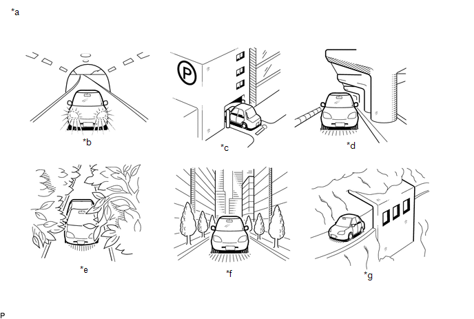
| *a | Example | *b | In a tunnel |
| *c | In a building | *d | Under an overpass |
| *e | On a forest or tree-lined path | *f | Between tall buildings |
| *g | Under a cliff or overhang | - | - |
OK:
The "No GPS signal" mark disappears.
| OK | | SYSTEM RETURNS TO NORMAL |
|
| 3. | CHECK GPS INFORMATION (OPERATION CHECK) |
| (a) Enter the "System Sensors Check" screen. Refer to Check GPS & Vehicle Sensors in Operation Check. Click here |
|
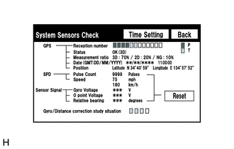
(b) Check how many of the following codes appear in the "Reception number" column.
HINT:
T or P appears.
OK:
At least 3 codes appear.
| OK | | REPLACE RADIO RECEIVER ASSEMBLY |
| NG | | PROCEED TO NEXT SUSPECTED AREA SHOWN IN PROBLEM SYMPTOMS TABLE |
READ NEXT:
 AVC-LAN Circuit
DESCRIPTION Each unit of the navigation system connected to the AVC-LAN (communication bus) transmits switch signals via AVC-LAN communication. If a short to +B or short to ground occurs in the AVC-LA
Stereo Component Amplifier Malfunction (B15A3)
DESCRIPTION This DTC is stored when a malfunction occurs in the stereo component amplifier assembly. DTC No. Detection Item DTC Detection Condition Trouble Area B15A3 Stereo Component A
Display Malfunction (B15A6,B15B0)
DESCRIPTION These DTCs are stored when a malfunction occurs in the multi-display assembly. DTC No. Detection Item DTC Detection Condition Trouble Area B15A6 Display Malfunction When a
SEE MORE:
Auto Down Operation does not Fully Open Power Window (Catch Protection Function is Activated)
DESCRIPTION If a door glass does not slide smoothly or a power window regulator motor assembly or door window regulator sub-assembly does not operate smoothly, the catch protection function may be triggered automatically, resulting in the auto down operation being unable to fully open the power wind
Removal
REMOVAL CAUTION / NOTICE / HINT The necessary procedures (adjustment, calibration, initialization, or registration) that must be performed after parts are removed, installed, or replaced during brake booster pump assembly removal/installation are shown below. Necessary Procedures After Parts Removed
