Lexus ES: System Diagram
Lexus ES (XZ10) Service Manual / Engine & Hybrid System / A25a-fks (emission Control) / Emission Control System / System Diagram
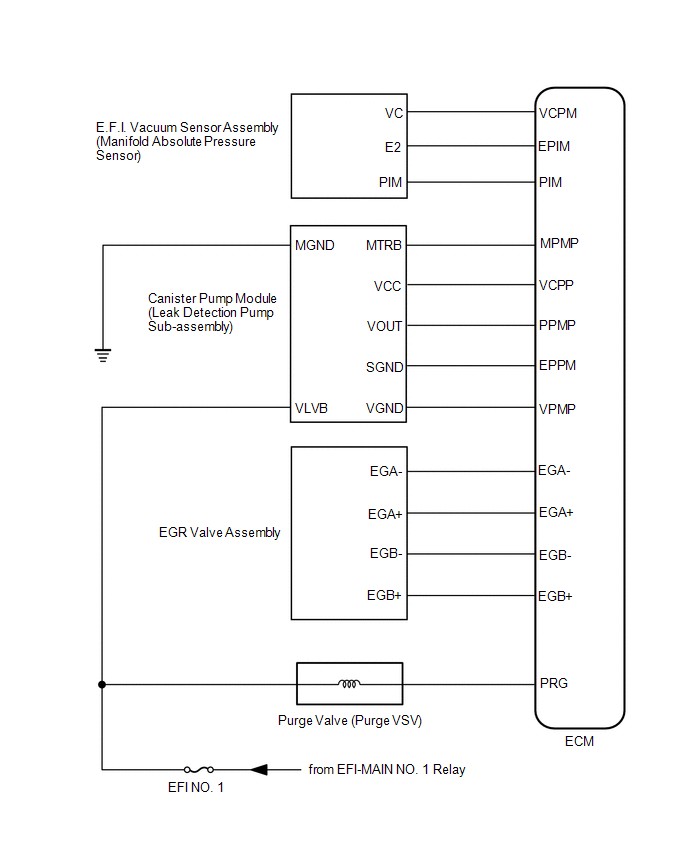
SYSTEM DIAGRAM
.png)
| *1 | Purge Valve (Purge VSV) | *2 | Fuel Tank Cap Assembly |
| *3 | Fuel Tank Assembly | *4 | Canister Filter |
| *5 | Fuel Cut-off Valve | *6 | ECM |
| *7 | Canister Pump Module (Leak Detection Pump Sub-assembly) | *8 | Pump Motor |
| *9 | Canister Pressure Sensor | *10 | Vent Valve |
| *11 | Canister (Charcoal Canister Assembly) | - | - |
| *a | to Intake Manifold | *b | Purge Line |
| *c | Air Line | *d | Vent Line |
READ NEXT:
 On-vehicle Inspection
ON-VEHICLE INSPECTION CAUTION / NOTICE / HINT CAUTION: To prevent injury due to contact with an operating V-ribbed belt or cooling fan, keep your hands and clothing away from the V-ribbed belt and coo
Components
COMPONENTS ILLUSTRATION *1 PCV VALVE (VENTILATION VALVE SUB-ASSEMBLY) - -
SEE MORE:
Fuel Rail Pressure Sensor "A" Signal Stuck in Range (P01902A,P019064)
DESCRIPTION Refer to DTC P019011. Click here DTC No. Detection Item DTC Detection Condition Trouble Area MIL Memory Note P01902A Fuel Rail Pressure Sensor "A" Signal Stuck in Range When target high pressure side fuel pressure changes, the change in fuel pressure sensor value
Front Left Sensor Malfunction (C1AE1)
DESCRIPTION The front corner ultrasonic sensor LH is installed to the front bumper. The clearance warning ECU assembly detects obstacles based on signals received from the front corner ultrasonic sensor LH. If the front corner ultrasonic sensor LH has an open circuit or other malfunction, it will no
© 2016-2026 Copyright www.lexguide.net
