Lexus ES: Steering Angle Sensor (C1297)
DESCRIPTION
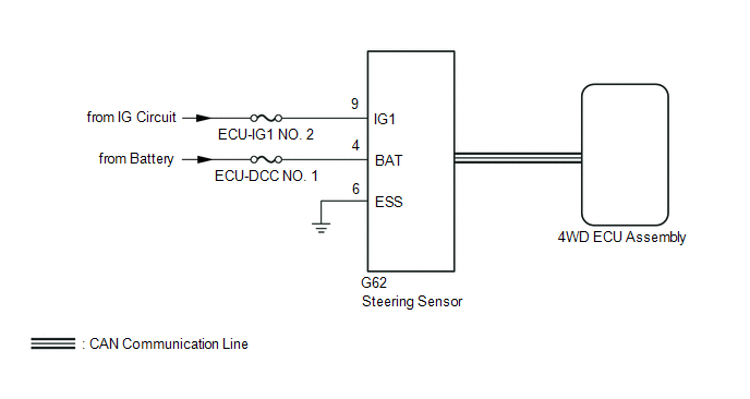
The 4WD ECU assembly determines that the vehicle is turning based on the signals sent from the steering sensor.
The steering sensor signal is sent to the 4WD ECU assembly via CAN communication.
| DTC No. | Detection Item | DTC Detection Condition | Trouble Area |
|---|---|---|---|
| C1297 | Steering Angle Sensor | When voltage of 4WD ECU assembly IG terminal is 9.5 V or more, and steering sensor malfunction signal is received. |
|
WIRING DIAGRAM
CAUTION / NOTICE / HINT
NOTICE:
Inspect the fuses for circuits related to this system before performing the following inspection procedure.
PROCEDURE
| 1. | CHECK FOR DTC |
(a) Clear the DTC.
Chassis > Four Wheel Drive > Clear DTCs(b) Turn the engine switch off.
(c) Turn the engine switch on (IG) again and check that no CAN communication system DTC(s) is output.
Click here .gif)
(d) Start the engine.
(e) Drive the vehicle at a speed of 35 km/h (24 mph), turn the steering wheel to the right and left and check that no electronically controlled brake system DTC (steering sensor) is output.
Chassis > Brake/EPB > Trouble Codes| Result | Proceed to |
|---|---|
| Neither CAN communication system DTC nor electronically controlled brake system DTC is output | A |
| CAN communication system DTC is output | B |
| Electronically controlled brake system DTC (steering sensor) is output | C |
HINT:
When DTCs indicating a CAN communication system malfunction are output, repair the CAN communication system before repairing each corresponding sensor.
| B | .gif) | GO TO CAN COMMUNICATION SYSTEM (HOW TO PROCEED WITH TROUBLESHOOTING) |
| C | | REPAIR CIRCUIT INDICATED BY OUTPUT CODE (ELECTRONICALLY CONTROLLED BRAKE SYSTEM) |
|
.gif)
| 2. | CHECK HARNESS AND CONNECTOR (POWER SOURCE TERMINAL) |
(a) Remove the steering wheel assembly and the lower steering column cover sub-assembly.
(b) Make sure that there is no looseness at the locking part and the connecting part of the connectors.
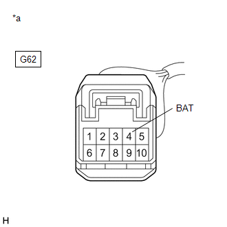
| (c) Disconnect the G62 steering sensor connector. |
|
(d) Measure the voltage according to the value(s) in the table below.
Standard Voltage:
| Tester Connection | Condition | Specified Condition |
|---|---|---|
| G62-4 (BAT) - Body ground | Always | 11 to 14 V |
| NG | | REPAIR OR REPLACE HARNESS OR CONNECTOR |
|
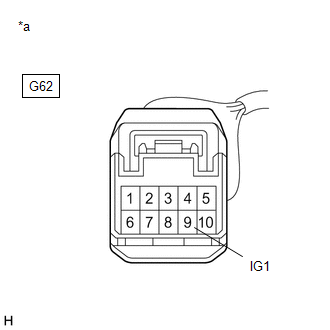
| 3. | CHECK TERMINAL VOLTAGE (IG1 TERMINAL) |
(a) Turn the engine switch on (IG).
| (b) Measure the voltage according to the value(s) in the table below. |
|
Standard Voltage:
| Tester Connection | Condition | Specified Condition |
|---|---|---|
| G62-9 (IG1) - Body ground | Engine switch on (IG) | 11 to 14 V |
| NG | | REPAIR OR REPLACE HARNESS OR CONNECTOR (IG1 CIRCUIT) |
|
| 4. | CHECK HARNESS AND CONNECTOR (ESS TERMINAL) |
(a) Turn the engine switch off.
(b) Measure the resistance according to the value(s) in the table below.
Standard Resistance:
| Tester Connection | Condition | Specified Condition |
|---|---|---|
| G62-6 (ESS) - Body ground | Always | Below 1 Ω |
| NG | | REPAIR OR REPLACE HARNESS OR CONNECTOR |
|
| 5. | READ VALUE USING TECHSTREAM (STEERING ANGLE VALUE) |
(a) Connect the Techstream to the DLC3.
(b) Turn the engine switch on (IG).
(c) Turn the Techstream on.
(d) Enter the following menus: Chassis / Four Wheel Drive / Data List.
(e) Read the value displayed on the Techstream.
Chassis > Four Wheel Drive > Data List| Tester Display | Measurement Item | Range | Normal Condition | Diagnostic Note |
|---|---|---|---|---|
| Steering Angle Value | Steering angle value | Min.: -3276.8° Max.: 3276.7° | Increase: Left turn Decrease: Right turn | Changes in proportion with the amount of steering wheel rotation during steering operation. |
| Tester Display |
|---|
| Steering Angle Value |
OK:
The steering sensor value changes in accordance with the steering wheel movement.
| OK | | REPLACE 4WD ECU ASSEMBLY |
| NG | | REPLACE STEERING SENSOR |
READ NEXT:
 Linear Solenoid Circuit (C1298)
DESCRIPTION The 4WD ECU assembly receives signals from each sensor to control clutch fluid pressure for limiting the center differential operation, which distributes torque according to the driving co
Cancellation of 4WD Control (C1299)
DESCRIPTION This DTC is output if the heat generated by the transmission coupling assembly exceeds a certain amount or if the estimated oil temperature of the transfer exceeds a certain amount while d
Diameter of the Tire is not Uniform (C1337)
DESCRIPTION The 4WD ECU assembly outputs this DTC if a difference in tire size is detected. DTC No. Detection Item DTC Detection Condition Trouble Area C1337 Diameter of the Tire is not
SEE MORE:
Steering Angle Sensor Communication Stop Mode
DESCRIPTION Detection Item Symptom Trouble Area Steering Angle Sensor Communication Stop Mode Any of the following conditions are met:
Communication stop for "Spiral cable (Steering Angle Sensor)" is indicated on the "Communication Bus Check" screen of the Techstream.
Click here
Generator Inverter Actuator Stuck Open (P0A7A72)
DTC SUMMARY MALFUNCTION DESCRIPTION This DTC indicates that current does not flow as commanded due to a generator output circuit malfunction. The cause of this malfunction may be one of the following: Internal inverter malfunction
Inverter with converter assembly internal circuit malfunction
