Lexus ES: Sensor (Motor) Failure (B2341,B2344)
DESCRIPTION
When the sliding roof ECU (sliding roof drive gear sub-assembly) detects a motor malfunction and the sliding roof operation is stopped, DTC B2341 is stored.
When the sliding roof ECU (sliding roof drive gear sub-assembly) detects a gear position malfunction and the sliding roof operation is stopped, DTC B2344 is stored.
| DTC No. | Detection Item | DTC Detection Condition | Trouble Area |
|---|---|---|---|
| B2341 | Sensor (Motor) Failure | Sensor (motor) failure (The sliding roof ECU (sliding roof drive gear sub-assembly) enters fail-safe mode due to a problem with the motor) |
|
| B2344 | Position Failure | Position failure (The sliding roof ECU (sliding roof drive gear sub-assembly) enters fail-safe mode due to a problem with the gear position) |
|
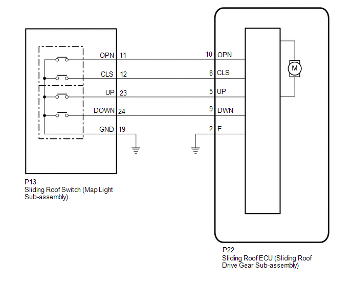
WIRING DIAGRAM
CAUTION / NOTICE / HINT
NOTICE:
-
If the sliding roof ECU (sliding roof drive gear sub-assembly) is removed and reinstalled or replaced, the sliding roof ECU (sliding roof drive gear sub-assembly) must be initialized.
Click here
.gif)
PROCEDURE
| 1. | CHECK SLIDING ROOF OPERATION |
(a) Check the sliding roof auto operation.
Click here
OK:
Auto operation operates normally.
| NG | .gif) | GO TO STEP 3 |
|
.gif)
| 2. | CHECK DTC OUTPUT |
(a) Clear the DTCs.
Body Electrical > Sliding Roof > Clear DTCs(b) Check for DTCs.
Body Electrical > Sliding Roof > Trouble CodesOK:
DTCs B2341 and B2344 are not output.
| OK | | USE SIMULATION METHOD TO CHECK |
| NG | | REPLACE SLIDING ROOF ECU (SLIDING ROOF DRIVE GEAR SUB-ASSEMBLY) |
| 3. | INITIALIZE SLIDING ROOF ECU (SLIDING ROOF DRIVE GEAR SUB-ASSEMBLY) |
(a) Check that the sliding roof ECU (sliding roof drive gear sub-assembly) can be initialized.
Click here
OK:
Sliding roof ECU (sliding roof drive gear sub-assembly) can be initialized.
| NG | | GO TO STEP 5 |
|
| 4. | CHECK DTC OUTPUT |
(a) Clear the DTCs.
Body Electrical > Sliding Roof > Clear DTCs(b) Check for DTCs.
Body Electrical > Sliding Roof > Trouble CodesOK:
DTCs B2341 and B2344 are not output.
| OK | | END (MALFUNCTION DUE TO INITIALIZATION FAILURE) |
| NG | | REPLACE SLIDING ROOF ECU (SLIDING ROOF DRIVE GEAR SUB-ASSEMBLY) |
| 5. | CHECK HARNESS AND CONNECTOR (SLIDING ROOF ECU (SLIDING ROOF DRIVE GEAR SUB-ASSEMBLY) - SLIDING ROOF SWITCH (MAP LIGHT SUB-ASSEMBLY) AND BODY GROUND) |
(a) Disconnect the P13 sliding roof switch (map light sub-assembly) connector.
(b) Disconnect the P22 sliding roof ECU (sliding roof drive gear sub-assembly) connector.
(c) Measure the resistance according to the value(s) in the table below.
Standard Resistance:
| Tester Connection | Condition | Specified Condition |
|---|---|---|
| P22-8 (CLS) - P13-12 (CLS) | Always | Below 1 Ω |
| P22-8 (CLS) or P13-12 (CLS) - Body ground | Always | 10 kΩ or higher |
| P22-10 (OPN) - P13-11 (OPN) | Always | Below 1 Ω |
| P22-10 (OPN) or P13-11 (OPN) - Body ground | Always | 10 kΩ or higher |
| P22-9 (DWN) - P13-24 (DOWN) | Always | Below 1 Ω |
| P22-9 (DWN) or P13-24 (DOWN) - Body ground | Always | 10 kΩ or higher |
| P22-5 (UP) - P13-23 (UP) | Always | Below 1 Ω |
| P22-5 (UP) or P13-23 (UP) - Body ground | Always | 10 kΩ or higher |
| P13-19 (GND) - Body ground | Always | Below 1 Ω |
| P22-2 (E) - Body ground | Always | Below 1 Ω |
| NG | | REPAIR OR REPLACE HARNESS OR CONNECTOR |
|
| 6. | INSPECT SLIDING ROOF SWITCH (MAP LIGHT SUB-ASSEMBLY) |
(a) Remove the sliding roof switch (map light sub-assembly).
Click here
(b) Inspect the sliding roof switch (map light sub-assembly).
Click here
| OK | | REPLACE SLIDING ROOF ECU (SLIDING ROOF DRIVE GEAR SUB-ASSEMBLY) |
| NG | | REPLACE SLIDING ROOF SWITCH (MAP LIGHT SUB-ASSEMBLY) |
READ NEXT:
 Switch Failure (B2342)
DESCRIPTION This DTC is stored when the sliding roof ECU (sliding roof drive gear sub-assembly) detects that the sliding roof switch (map light sub-assembly) is stuck for 30 seconds or more. DTC No
Position Initialization Incomplete (B2343)
DESCRIPTION This DTC is stored when the sliding roof ECU (sliding roof drive gear sub-assembly) has not been initialized. DTC No. Detection Item DTC Detection Condition Trouble Area B2343
Remote Control System does not Operate
DESCRIPTION The main body ECU (multiplex network body ECU) receives remote control signals from the driver door key cylinder or electrical key transmitter sub-assembly. Then, the main body ECU (multip
SEE MORE:
Yaw Rate Sensor (C1A46)
DESCRIPTION The blind spot monitor sensor receives yaw rate signals from the airbag sensor assembly (yaw rate and acceleration sensor) via CAN communication. Blind Spot Monitor Master DTC No. Detection Item DTC Detection Condition Trouble Area C1A46 Yaw Rate Sensor A fail flag is tr
Drive Motor "A" Phase U Current Sensor Circuit Short to Battery (P0BE512,...,P0BED1F)
DTC SUMMARY MALFUNCTION DESCRIPTION These DTCs indicate that the current sensor value is abnormal. The cause of this malfunction may be one of the following: Internal inverter malfunction
Inverter with converter assembly internal circuit malfunction
Inverter low-voltage circuit malfunction
