Lexus ES: Right Front Wheel Speed Sensor Internal Electronic Failure (C050649)
DESCRIPTION
When the system is starting up and the skid control ECU (brake actuator assembly) detects a speed sensor circuit malfunction via the speed sensor circuit self-diagnosis function, this DTC is stored.
| DTC No. | Detection Item | DTC Detection Condition | Trouble Area |
|---|---|---|---|
| C050649 | Right Front Wheel Speed Sensor Internal Electronic Failure | A circuit malfunction in the speed sensor is detected during the self test. |
|
*: w/ AVS
WIRING DIAGRAM
Refer to DTC C050612.
Click here .gif)
CAUTION / NOTICE / HINT
NOTICE:
-
After replacing the skid control ECU (brake actuator assembly), perform acceleration sensor zero point calibration and store system information memorization.
Click here
-
After replacing or removing and installing a speed sensor, perform Dealer Mode (Signal Check) inspection to confirm that the speed sensors are operating correctly.
Click here
PROCEDURE
| 1. | CHECK VEHICLE |
(a) Check if the vehicle is equipped with AVS.
| Result | Proceed to |
|---|---|
| w/o AVS | A |
| w/ AVS | B |
| B |  | GO TO STEP 10 |
|

| 2. | CHECK HARNESS AND CONNECTOR (SENSOR CIRCUIT) |
| (a) Make sure that there is no looseness at the locking part and the connecting part of the connectors. OK: The connector is securely connected. |
|
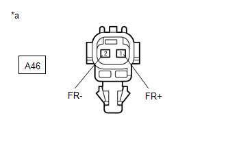
(b) Disconnect the A46 front speed sensor RH connector.
(c) Check both the connector case and the terminals for deformation and corrosion.
OK:
No deformation or corrosion.
(d) Turn the engine switch on (IG).
(e) Measure the voltage according to the value(s) in the table below.
Standard Voltage:
| Tester Connection | Condition | Specified Condition |
|---|---|---|
| A46-1 (FR+) - A46-2 (FR-) | Engine switch on (IG) | 11 to 14 V |
| NG | | GO TO STEP 6 |
|
| 3. | CHECK HARNESS AND CONNECTOR (SENSOR POWER SOURCE CIRCUIT) |
| (a) Make sure that there is no looseness at the locking part and the connecting part of the connectors. OK: The connector is securely connected. |
|
(b) Disconnect the A46 front speed sensor RH connector.
(c) Check both the connector case and the terminals for deformation and corrosion.
OK:
No deformation or corrosion.
(d) Measure the voltage according to the value(s) in the table below.
Standard Voltage:
| Tester Connection | Condition | Specified Condition |
|---|---|---|
| A46-1 (FR+) - Body ground | Engine switch off | Below 1.5 V |
| NG | | GO TO STEP 5 |
|
| 4. | CHECK HARNESS AND CONNECTOR (FRONT SPEED SENSOR RH - BRAKE ACTUATOR ASSEMBLY) |
(a) Make sure that there is no looseness at the locking part and the connecting part of the connectors.
OK:
The connector is securely connected.
(b) Disconnect the A40 skid control ECU (brake actuator assembly) connector.
(c) Disconnect the A46 front speed sensor RH connector.
(d) Check both the connector case and the terminals for deformation and corrosion.
OK:
No deformation or corrosion.
(e) Measure the resistance according to the value(s) in the table below.
Standard Resistance:
| Tester Connection | Condition | Specified Condition |
|---|---|---|
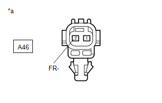
| A46-2 (FR-) or A40-26 (FR-) - Body ground | Always | 10 kΩ or higher |
| OK | | REPLACE FRONT SPEED SENSOR RH |
| NG | | REPAIR OR REPLACE HARNESS OR CONNECTOR |
| 5. | CHECK HARNESS AND CONNECTOR (FRONT SPEED SENSOR RH - BRAKE ACTUATOR ASSEMBLY) |
| (a) Make sure that there is no looseness at the locking part and the connecting part of the connectors. OK: The connector is securely connected. |
|
(b) Disconnect the A40 skid control ECU (brake actuator assembly) connector.
(c) Disconnect the A46 front speed sensor RH connector.
(d) Check both the connector case and the terminals for deformation and corrosion.
OK:
No deformation or corrosion.
(e) Measure the voltage according to the value(s) in the table below.
Standard Voltage:
| Tester Connection | Condition | Specified Condition |
|---|---|---|
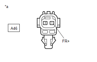
| A46-1 (FR+) - Body ground | Always | Below 1.5 V |
| OK | | REPLACE BRAKE ACTUATOR ASSEMBLY |
| NG | | REPAIR OR REPLACE HARNESS OR CONNECTOR |
| 6. | CHECK HARNESS AND CONNECTOR (SENSOR POWER SOURCE CIRCUIT) |
| (a) Make sure that there is no looseness at the locking part and the connecting part of the connectors. OK: The connector is securely connected. |
|
(b) Disconnect the A46 front speed sensor RH connector.
(c) Check both the connector case and the terminals for deformation and corrosion.
OK:
No deformation or corrosion.
(d) Turn the engine switch on (IG).
(e) Measure the voltage according to the value(s) in the table below.
Standard Voltage:
| Tester Connection | Condition | Specified Condition |
|---|---|---|
| A46-1 (FR+) - Body ground | Engine switch on (IG) | 11 to 14 V |
| NG | | GO TO STEP 9 |
|
| 7. | CHECK HARNESS AND CONNECTOR (FRONT SPEED SENSOR RH - BRAKE ACTUATOR ASSEMBLY) |
| (a) Make sure that there is no looseness at the locking part and the connecting part of the connectors. OK: The connector is securely connected. |
|
(b) Disconnect the A40 skid control ECU (brake actuator assembly) connector.
(c) Disconnect the A46 front speed sensor RH connector.
(d) Check both the connector case and the terminals for deformation and corrosion.
OK:
No deformation or corrosion.
(e) Measure the voltage according to the value(s) in the table below.
Standard Voltage:
| Tester Connection | Condition | Specified Condition |
|---|---|---|
| A46-2 (FR-) - Body ground | Always | Below 1.5 V |
| NG | | REPAIR OR REPLACE HARNESS OR CONNECTOR |
|
| 8. | CHECK HARNESS AND CONNECTOR (FRONT SPEED SENSOR RH - BRAKE ACTUATOR ASSEMBLY) |
(a) Make sure that there is no looseness at the locking part and the connecting part of the connectors.
OK:
The connector is securely connected.
(b) Disconnect the A40 skid control ECU (brake actuator assembly) connector.
(c) Disconnect the A46 front speed sensor RH connector.
(d) Check both the connector case and the terminals for deformation and corrosion.
OK:
No deformation or corrosion.
(e) Measure the resistance according to the value(s) in the table below.
Standard Resistance:
| Tester Connection | Condition | Specified Condition |
|---|---|---|
| A46-2 (FR-) - A40-26 (FR-) | Always | Below 1 Ω |
| A46-1 (FR+) or A40-21 (FR+) - A46-2 (FR-) - A40-26 (FR-) | Always | 10 kΩ or higher |
| OK | | REPLACE BRAKE ACTUATOR ASSEMBLY |
| NG | | REPAIR OR REPLACE HARNESS OR CONNECTOR |
| 9. | CHECK HARNESS AND CONNECTOR (FRONT SPEED SENSOR RH - BRAKE ACTUATOR ASSEMBLY) |
(a) Make sure that there is no looseness at the locking part and the connecting part of the connectors.
OK:
The connector is securely connected.
(b) Disconnect the A40 skid control ECU (brake actuator assembly) connector.
(c) Disconnect the A46 front speed sensor RH connector.
(d) Check both the connector case and the terminals for deformation and corrosion.
OK:
No deformation or corrosion.
(e) Measure the resistance according to the value(s) in the table below.
Standard Resistance:
| Tester Connection | Condition | Specified Condition |
|---|---|---|
| A46-1 (FR+) - A40-21 (FR+) | Always | Below 1 Ω |
| A46-1 (FR+) or A40-21 (FR+) - Body ground | Always | 10 kΩ or higher |
| OK | | REPLACE BRAKE ACTUATOR ASSEMBLY |
| NG | | REPAIR OR REPLACE HARNESS OR CONNECTOR |
| 10. | CHECK HARNESS AND CONNECTOR (SENSOR CIRCUIT) |
| (a) Make sure that there is no looseness at the locking part and the connecting part of the connectors. OK: The connector is securely connected. |
|
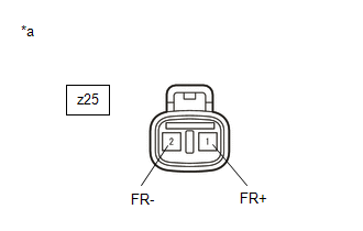
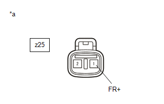
(b) Disconnect the z25 skid control sensor wire with suspension control RH connector.
(c) Check both the connector case and the terminals for deformation and corrosion.
OK:
No deformation or corrosion.
(d) Turn the engine switch on (IG).
(e) Measure the voltage according to the value(s) in the table below.
Standard Voltage:
| Tester Connection | Condition | Specified Condition |
|---|---|---|
| z25-1 (FR+) - z25-2 (FR-) | Engine switch on (IG) | 11 to 14 V |
| NG | | GO TO STEP 16 |
|
| 11. | CHECK HARNESS AND CONNECTOR (SENSOR POWER SOURCE CIRCUIT) |
| (a) Make sure that there is no looseness at the locking part and the connecting part of the connectors. OK: The connector is securely connected. |
|
(b) Disconnect the z25 skid control sensor wire with suspension control RH connector.
(c) Check both the connector case and the terminals for deformation and corrosion.
OK:
No deformation or corrosion.
(d) Measure the voltage according to the value(s) in the table below.
Standard Voltage:
| Tester Connection | Condition | Specified Condition |
|---|---|---|
| z25-1 (FR+) - Body ground | Engine switch off | Below 1.5 V |
| NG | | GO TO STEP 14 |
|
| 12. | INSPECT SKID CONTROL SENSOR WIRE WITH SUSPENSION CONTROL RH |
| (a) Make sure that there is no looseness at the locking part and the connecting part of the connectors. OK: The connector is securely connected. |
|
(b) Disconnect the z25 skid control sensor wire with suspension control RH connector.
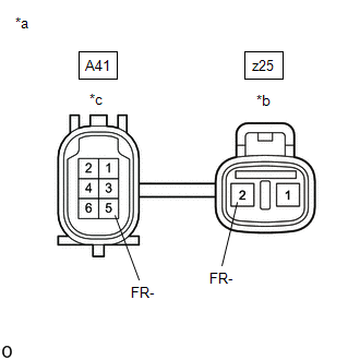
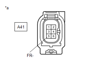
(c) Disconnect the A41 skid control sensor wire with suspension control RH connector.
(d) Check both the connector case and the terminals for deformation and corrosion.
OK:
No deformation or corrosion.
(e) Measure the resistance according to the value(s) in the table below.
Standard Resistance:
| Tester Connection | Condition | Specified Condition |
|---|---|---|
| z25-2 (FR-) or A41-5 (FR-) - Body ground and other terminals | Always | 10 kΩ or higher |
| NG | | REPLACE SKID CONTROL SENSOR WIRE WITH SUSPENSION CONTROL RH |
|
| 13. | CHECK HARNESS AND CONNECTOR (SKID CONTROL SENSOR WIRE WITH SUSPENSION CONTROL RH - BRAKE ACTUATOR ASSEMBLY) |
(a) Make sure that there is no looseness at the locking part and the connecting part of the connectors.
OK:
The connector is securely connected.
(b) Disconnect the A40 skid control ECU (brake actuator assembly) connector.
(c) Disconnect the A41 skid control sensor wire with suspension control RH connector.
(d) Check both the connector case and the terminals for deformation and corrosion.
OK:
No deformation or corrosion.
(e) Measure the resistance according to the value(s) in the table below.
Standard Resistance:
| Tester Connection | Condition | Specified Condition |
|---|---|---|
| A41-5 (FR-) or A40-26 (FR-) - Body ground | Always | 10 kΩ or higher |
| OK | | REPLACE FRONT SPEED SENSOR RH |
| NG | | REPAIR OR REPLACE HARNESS OR CONNECTOR |
| 14. | CHECK HARNESS AND CONNECTOR (SENSOR POWER SOURCE CIRCUIT) |
| (a) Make sure that there is no looseness at the locking part and the connecting part of the connectors. OK: The connector is securely connected. |
|
(b) Disconnect the A41 skid control sensor wire with suspension control RH connector.
(c) Check both the connector case and the terminals for deformation and corrosion.
OK:
No deformation or corrosion.
(d) Measure the voltage according to the value(s) in the table below.
Standard Voltage:
| Tester Connection | Condition | Specified Condition |
|---|---|---|
| A41-6 (FR+) - Body ground | Engine switch off | Below 1.5 V |
| OK | | REPLACE SKID CONTROL SENSOR WIRE WITH SUSPENSION CONTROL RH |
|
| 15. | CHECK HARNESS AND CONNECTOR (SKID CONTROL SENSOR WIRE WITH SUSPENSION CONTROL RH - BRAKE ACTUATOR ASSEMBLY) |
| (a) Make sure that there is no looseness at the locking part and the connecting part of the connectors. OK: The connector is securely connected. |
|
(b) Disconnect the A40 skid control ECU (brake actuator assembly) connector.
(c) Disconnect the A41 skid control sensor wire with suspension control RH connector.
(d) Check both the connector case and the terminals for deformation and corrosion.
OK:
No deformation or corrosion.
(e) Measure the voltage according to the value(s) in the table below.
Standard Voltage:
| Tester Connection | Condition | Specified Condition |
|---|---|---|
| A41-6 (FR+) - Body ground | Always | Below 1.5 V |
| OK | | REPLACE BRAKE ACTUATOR ASSEMBLY |
| NG | | REPAIR OR REPLACE HARNESS OR CONNECTOR |
| 16. | CHECK HARNESS AND CONNECTOR (SENSOR CIRCUIT) |
| (a) Make sure that there is no looseness at the locking part and the connecting part of the connectors. OK: The connector is securely connected. |
|
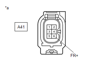
(b) Disconnect the A41 skid control sensor wire with suspension control RH connector.
(c) Check both the connector case and the terminals for deformation and corrosion.
OK:
No deformation or corrosion.
(d) Turn the engine switch on (IG).
(e) Measure the voltage according to the value(s) in the table below.
Standard Voltage:
| Tester Connection | Condition | Specified Condition |
|---|---|---|
| A41-6 (FR+) - A41-5 (FR-) | Engine switch on (IG) | 11 to 14 V |
| OK | | REPLACE SKID CONTROL SENSOR WIRE WITH SUSPENSION CONTROL RH |
|
| 17. | CHECK HARNESS AND CONNECTOR (SENSOR POWER SOURCE CIRCUIT) |
| (a) Make sure that there is no looseness at the locking part and the connecting part of the connectors. OK: The connector is securely connected. |
|
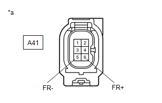
(b) Disconnect the A41 skid control sensor wire with suspension control RH connector.
(c) Check both the connector case and the terminals for deformation and corrosion.
OK:
No deformation or corrosion.
(d) Turn the engine switch on (IG).
(e) Measure the voltage according to the value(s) in the table below.
Standard Voltage:
| Tester Connection | Condition | Specified Condition |
|---|---|---|
| A41-6 (FR+) - Body ground | Engine switch on (IG) | 11 to 14 V |
| NG | | GO TO STEP 20 |
|
| 18. | CHECK HARNESS AND CONNECTOR (SKID CONTROL SENSOR WIRE WITH SUSPENSION CONTROL RH - BRAKE ACTUATOR ASSEMBLY) |
| (a) Make sure that there is no looseness at the locking part and the connecting part of the connectors. OK: The connector is securely connected. |
|
(b) Disconnect the A40 skid control ECU (brake actuator assembly) connector.
(c) Disconnect the A41 skid control sensor wire with suspension control RH connector.
(d) Check both the connector case and the terminals for deformation and corrosion.
OK:
No deformation or corrosion.
(e) Measure the voltage according to the value(s) in the table below.
Standard Voltage:
| Tester Connection | Condition | Specified Condition |
|---|---|---|
| A41-5 (FR-) - Body ground | Always | Below 1.5 V |
| NG | | REPAIR OR REPLACE HARNESS OR CONNECTOR |
|
| 19. | CHECK HARNESS AND CONNECTOR (SKID CONTROL SENSOR WIRE WITH SUSPENSION CONTROL RH - BRAKE ACTUATOR ASSEMBLY) |
(a) Make sure that there is no looseness at the locking part and the connecting part of the connectors.
OK:
The connector is securely connected.
(b) Disconnect the A40 skid control ECU (brake actuator assembly) connector.
(c) Disconnect the A41 skid control sensor wire with suspension control RH connector.
(d) Check both the connector case and the terminals for deformation and corrosion.
OK:
No deformation or corrosion.
(e) Measure the resistance according to the value(s) in the table below.
Standard Resistance:
| Tester Connection | Condition | Specified Condition |
|---|---|---|
| A41-5 (FR-) - A40-26 (FR-) | Always | Below 1 Ω |
| A41-6 (FR+) or A40-21 (FR+) - A41-5 (FR-) or A40-26 (FR-) | Always | 10 kΩ or higher |
| OK | | REPLACE BRAKE ACTUATOR ASSEMBLY |
| NG | | REPAIR OR REPLACE HARNESS OR CONNECTOR |
| 20. | CHECK HARNESS AND CONNECTOR (SKID CONTROL SENSOR WIRE WITH SUSPENSION CONTROL RH - BRAKE ACTUATOR ASSEMBLY) |
(a) Make sure that there is no looseness at the locking part and the connecting part of the connectors.
OK:
The connector is securely connected.
(b) Disconnect the A40 skid control ECU (brake actuator assembly) connector.
(c) Disconnect the A41 skid control sensor wire with suspension control RH connector.
(d) Check both the connector case and the terminals for deformation and corrosion.
OK:
No deformation or corrosion.
(e) Measure the resistance according to the value(s) in the table below.
Standard Resistance:
| Tester Connection | Condition | Specified Condition |
|---|---|---|
| A41-6 (FR+) - A40-21 (FR+) | Always | Below 1 Ω |
| A41-6 (FR+) or A40-21 (FR+) - Body ground | Always | 10 kΩ or higher |
| OK | | REPLACE BRAKE ACTUATOR ASSEMBLY |
| NG | | REPAIR OR REPLACE HARNESS OR CONNECTOR |
READ NEXT:
 Right Rear Wheel Speed Sensor Circuit Short to Battery (C051212)
DESCRIPTION Each speed sensor detects wheel speed and sends signals to the skid control ECU (brake actuator assembly). These signals are used by the ABS control. The speed sensor detects the magnetic
Right Rear Wheel Speed Sensor Circuit Short to Battery (C051212)
DESCRIPTION Each speed sensor detects wheel speed and sends signals to the skid control ECU (brake actuator assembly). These signals are used by the ABS control. The speed sensor detects the magnetic
Right Rear Wheel Speed Sensor Circuit Short to Ground or Open (C051214)
DESCRIPTION Refer to DTC C051212 Click here DTC No. Detection Item DTC Detection Condition Trouble Area C051214 Right Rear Wheel Speed Sensor Circuit Short to Ground or Open A short
SEE MORE:
Inspection
INSPECTION PROCEDURE 1. INSPECT FLOW SHUTTING VALVE (WATER BY-PASS HOSE ASSEMBLY) (a) Measure the resistance according to the value(s) in the table below. Standard Resistance: Tester Connection Condition Specified Condition 1 - 2 20°C (68°F) 22 to 28 Ω If the result is not a
Power Mirror Surface Position is not Memorized
DESCRIPTION If any of the M1, M2 or M3 seat memory switch is pressed, the outer mirror control ECU assembly (driver door) detects the switch operation and sends the seat memory switch signal to the main body ECU (multiplex network body ECU) via CAN communication. On receiving the seat memory switch
