Lexus ES: Removal
REMOVAL
CAUTION / NOTICE / HINT
The necessary procedures (adjustment, calibration, initialization, or registration) that must be performed after parts are removed and installed, or replaced during ignition coil assembly or spark plug removal/installation are shown below.
Necessary Procedures After Parts Removed/Installed/Replaced| Replaced Part or Performed Procedure | Necessary Procedure | Effect/Inoperative Function when Necessary Procedure not Performed | Link |
|---|---|---|---|
| Inspection after repair |
| |
NOTICE:
This procedure includes the removal of small-head bolts. Refer to Small-Head Bolts of Basic Repair Hint to identify the small-head bolts.
Click here .gif)
PROCEDURE
1. REMOVE NO. 1 ENGINE COVER SUB-ASSEMBLY
Click here
2. REMOVE IGNITION COIL ASSEMBLY
| (a) Disconnect the 4 ignition coil assembly connectors. |
|
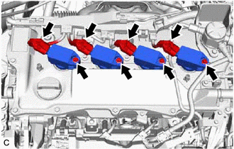
(b) Using an 8 mm socket wrench, remove the 4 bolts and 4 ignition coil assemblies from the cylinder head cover sub-assembly.
NOTICE:
If an ignition coil assembly has been struck or dropped, replace it.
HINT:
Arrange the removed parts in the correct order.
3. REMOVE SPARK PLUG
Click here
READ NEXT:
 Installation
INSTALLATION CAUTION / NOTICE / HINT NOTICE: This procedure includes the installation of small-head bolts. Refer to Small-Head Bolts of Basic Repair Hint to identify the small-head bolts. Click here
Parts Location
PARTS LOCATION ILLUSTRATION *1 ECM *2 NO. 1 ENGINE ROOM RELAY BLOCK AND NO. 1 JUNCTION BLOCK ASSEMBLY - INJ FUSE *3 IGNITION COIL ASSEMBLY *4 SPARK PLUG
SEE MORE:
Winter driving tips
Carry out the necessary preparations
and inspections before driving
the vehicle in winter. Always drive
the vehicle in a manner appropriate
to the prevailing weather conditions.
Preparation for winter
Use fluids that are appropriate to
the prevailing outside temperatures.
Engine oil
Pressure Control Solenoid "G" Circuit Short to Ground or Open (P280714)
DESCRIPTION Refer to DTC P280712. Click here DTC No. Detection Item DTC Detection Condition Trouble Area MIL Memory Note P280714 Pressure Control Solenoid "G" Circuit Short to Ground or Open While the vehicle is being driven so that gear changes occur, a short to ground or o
