Lexus ES: Operation Method
OPERATION METHOD
PROCEDURE
1. PRECAUTION
Click here .gif)
2. SEPARATE REAR SEAT CUSHION ASSEMBLY
Click here
3. REMOVE REAR SEAT CUSHION LOCK HOOK
Click here
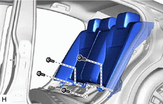
4. SEPARATE REAR SEATBACK ASSEMBLY
| (a) Remove the 4 bolts from rear seatback assembly. |
|
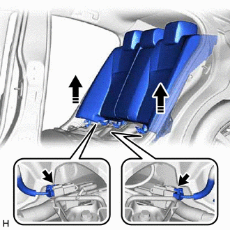
| (b) Lift the rear seatback assembly to the extent that the connector is visible. NOTICE: Be careful not to damage the rear seatback assembly. |
|
5. PARKING BRAKE FORCED RELEASE
CAUTION:
Work on a level surface to ensure safety.
NOTICE:
- To release the parking brake, follow the procedure for when using SST.
- If the parking brake cannot be released, follow the procedure for when not using SST.
-
When moving the vehicle after releasing the parking brake, install all parts and do not connect the 2 connectors shown in the illustration.
-
If the engine switch is on (IG) or the engine is started with the 2 connectors disconnected, a DTC may be stored. Clear any DTCs after performing work.
Click here
(a) When using SST:
(1) Park the vehicle on a level surface and move the shift lever to P.
(2) Turn the engine switch off and chock the wheels.
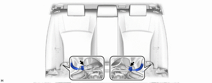
(3) Disconnect the 2 connectors shown in the illustration.
(4) Connect SST (09756-48020) to SST (09756-48070).
SST: 09756-48020
SST: 09756-48070
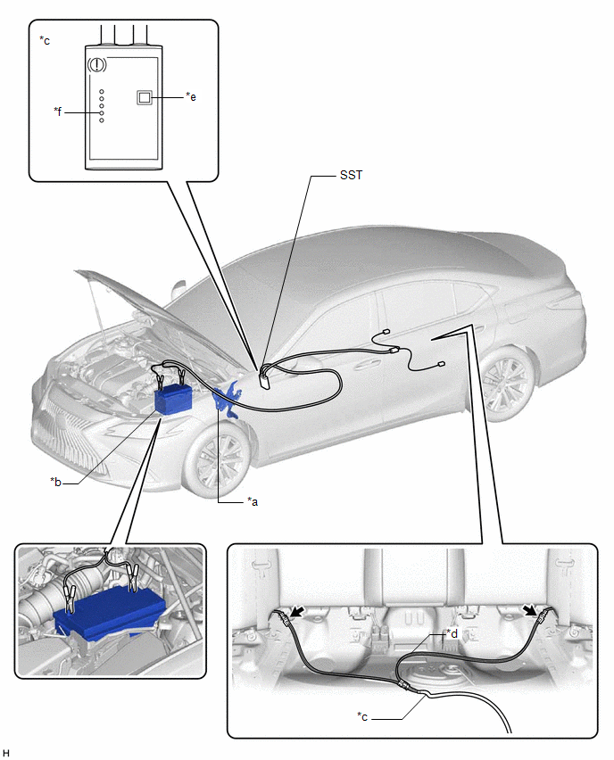
| *a | Brake Pedal | *b | Battery |
| *c | SST (09756-48020) | *d | SST (09756-48070) |
| *e | Release Button | *f | Finished Light |
.png) | Connector | - | - |
(5) Connect SST (09756-48070) to the 2 connectors inside of the vehicle.
(6) Connect SST (09756-48020) to the battery from the outside of the vehicle.
(7) Push the release button on SST (09756-48020) with the brake pedal depressed.
CAUTION:
The vehicle may suddenly move when the parking brake is released. Make sure to perform the release operation with the brake pedal depressed.
HINT:
- Confirm that the parking brake is operating by listening for operation sounds.
- If no operation sounds are heard, push the release button on SST (09756-48020) with the brake pedal depressed.
- The parking brake may not release if the battery voltage is too low. In this case, perform the release operation again using a fully charged or new battery.
(8) When the finished light of SST (09756-48020) illuminates, release the brake pedal.
(9) Move the vehicle forward and rearward to check that the parking brake is released.
CAUTION:
Be careful when performing this operation. The vehicle may suddenly move.
NOTICE:
- When moving the vehicle after releasing the parking brake, check that the 2 connectors are disconnected.
- The brake warning light (yellow) will illuminate when the vehicle is moved after releasing the parking brake.
(b) When not using SST:
NOTICE:
Perform the following procedure only when the parking brake cannot be released using SST.
HINT:
- Use the same procedure for the RH side and LH side.
- The following procedure is for the LH side.
(1) Park the vehicle on a level surface and check that the shift lever is in P.
(2) Turn the engine switch off and check that the wheels are chocked.
(3) Check that the 2 connectors shown in the illustration have been disconnected.
(4) Remove the rear wheel.
Click here
CAUTION:
When using a jack to lift the vehicle, make sure to support the vehicle using safety stands. Do not work on the vehicle with it supported only by a jack.
Click here
(5) Disconnect the No. 2 parking brake wire assembly connector from the parking brake actuator assembly.
Click here
(6) Remove the parking brake actuator assembly from the rear disc brake cylinder assembly.
Click here
| (7) Insert an L-shaped T45 "TORX" wrench into the rear disc brake cylinder assembly. |
|
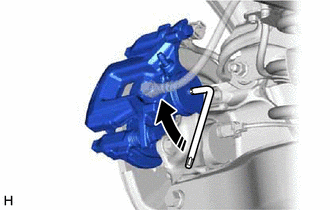
(8) Turn the L-shaped T45 "TORX" wrench 2 full rotations clockwise to release the parking brake lock.
NOTICE:
-
When moving the vehicle after releasing the parking brake, install all parts and do not connect the 2 connectors shown in the illustration.
- The brake warning light (yellow) will illuminate when the vehicle is moved after releasing the parking brake.
READ NEXT:
 Operation Method
OPERATION METHOD PROCEDURE 1. PRECAUTION Click here 2. TURN BACK LUGGAGE COMPARTMENT TRIM COVER RH (a) Turn back the luggage compartment trim cover RH as shown in the illustration. Remove in
Parking Brake System
PrecautionPRECAUTION NOTICE:
If the battery is connected, the parking brake will operate when the electric parking brake switch assembly is pulled to the lock side even if the engine switch (for G
SEE MORE:
Precaution
PRECAUTION 1.PRECAUTION WHEN REMOVING/INSTALLING INVERTER WITH CONVERTER ASSEMBLY CAUTION:
Do not push down or apply excessive force to the inverter with converter assembly.
Be careful not to injure yourself on the edges of the inverter with converter assembly when performing work.
NOTICE: O
Drive Motor "A" Inverter Voltage Sensor(VH) Circuit Voltage Above Threshold (P0C7917)
DTC SUMMARY MALFUNCTION DESCRIPTION If an overvoltage malfunction occurs in the motor inverter or generator inverter, the motor generator control ECU (MG ECU) detects the malfunction and stores this DTC. The cause of this malfunction may be one of the following: Area Main Malfunction Descriptio
