Lexus ES: Open Circuit in ABS Solenoid Relay Circuit (C146E,C146F)
DESCRIPTION
The ABS solenoid relay built into the skid control ECU (brake booster with master cylinder assembly) supplies power to the holding solenoid and reduction solenoid.
The ABS solenoid relay is operated 1.5 seconds after the power switch is turned on (IG), and is turned off if an open or short in the ABS solenoid is detected during self-diagnosis when the vehicle starts driving.
| DTC No. | Detection Item | INF Code | DTC Detection Condition | Trouble Area | MIL | Note |
|---|---|---|---|---|---|---|
| C146E | Open Circuit in ABS Solenoid Relay Circuit | 1135 | Either of the following is detected:
|
| Comes on |
|
| C146F | Short Circuit in ABS Solenoid Relay Circuit | 1136 | When operation of the ABS solenoid relay is not requested, the ABS solenoid relay operates (+BS terminal voltage is 3.5 V or more) for 4.5 seconds or more. | Skid control ECU (brake booster with master cylinder assembly) | Comes on |
|
MONITOR DESCRIPTION
The skid control ECU (brake booster with master cylinder assembly) monitors the voltage of the ABS solenoid.
When the ABS solenoid relay is instructed to be on and the voltage of the ABS solenoid is within the range of an open circuit malfunction, or when the ABS solenoid relay is instructed to be off and the voltage of the ABS solenoid is within the range of a short circuit malfunction, an open circuit or short circuit is judged respectively and the MIL is illuminated and a DTC is stored.
MONITOR STRATEGY
| Related DTCs | C146E (Case 1): ABS solenoid power supply relay circuit low C146E (Case 2): ABS solenoid power supply relay circuit low C146F (Case 1): ABS solenoid power supply relay circuit high C146F (Case 2): ABS solenoid power supply relay circuit high |
| Required Sensors/Components(Main) | Brake actuator assembly |
| Required Sensors/Components(Related) | Skid control ECU (brake booster with master cylinder assembly) |
| Frequency of Operation | Continuous: C146E (Case 1), C146F (Case 1) During initial checking: C146E (Case 2), C146F (Case 2) |
| Duration | 0.2 seconds: C146E (Case 1 and 2) 2 seconds: C146F (Case 2) 4.5 seconds: C146F (Case 1) |
| MIL Operation | Immediately |
| Sequence of Operation | None |
TYPICAL ENABLING CONDITIONS
All| Monitor runs whenever the following DTCs are not stored | None |
| All of the following conditions are met | A, B and C |
| A. Skid control ECU (brake booster with master cylinder assembly) state | Normal |
| B. Command to ABS solenoid power supply relay | On |
| C. Either of the following conditions is met | a or b |
| a. Both of the following conditions are met | - |
| Power switch | Off |
| Brake system voltage 1 (VM1) | Higher than 6.92 V |
| b. All of the following conditions are met | - |
| Power switch | On (READY) |
| Brake system voltage 1 (VM1) | Higher than 6.92 V |
| IG1 voltage | Higher than 9.54 V |
| All of the following conditions are met | - |
| Skid control ECU (brake booster with master cylinder assembly) state | Initial check |
| Command to ABS solenoid power supply relay | On |
| Brake system voltage 1 (VM1) | Higher than 6.92 V |
| Both of the following conditions are met | - |
| Skid control ECU (brake booster with master cylinder assembly) state | Normal |
| Command to ABS solenoid power supply relay | Off |
| Both of the following conditions are met | - |
| Skid control ECU (brake booster with master cylinder assembly) state | Initial check |
| Command to ABS solenoid power supply relay | Off |
TYPICAL MALFUNCTION THRESHOLDS
C146E (Case 1 and 2)| Power supply for ABS solenoid | Less than 3.5 V |
| Power supply for ABS solenoid | 3.5 V or more |
COMPONENT OPERATING RANGE
C146E| All of the following conditions are met | - |
| Skid control ECU (brake booster with master cylinder assembly) state | Normal |
| Command to ABS solenoid power supply relay | On |
| Power supply for ABS solenoid | 3.5 V or more |
| All of the following conditions are met | - |
| Skid control ECU (brake booster with master cylinder assembly) state | Normal |
| Command to ABS solenoid power supply relay | Off |
| Power supply for ABS solenoid | Less than 3.5 V |
| All of the following conditions are met | - |
| Skid control ECU (brake booster with master cylinder assembly) state | Initial check |
| Command to ABS solenoid power supply relay | Off |
| Power supply for ABS solenoid | Less than 3.5 V |
CONFIRMATION DRIVING PATTERN
- Connect the Techstream to the DLC3.
- Turn the power switch on (IG).
- Turn the Techstream on.
- Clear the DTCs (even if no DTCs are stored, perform the clear DTC procedure).
- Turn the power switch off.
- Turn the power switch on (IG).
- Turn the Techstream on.
- Wait 4.5 seconds.
- Enter the following menus: Chassis / ABS/VSC/TRAC / Trouble Codes.
-
Read the DTCs.
HINT:
- If a DTC is output, the system is malfunctioning.
- If a DTC is not output, perform the following procedure.
-
If the DTCs are not output, perform a universal trip and check for permanent DTCs.
Click here
.gif)
HINT:
- If a permanent DTC is output, the system is malfunctioning.
- If no permanent DTCs are output, the system is normal.
WIRING DIAGRAM
Refer to DTCs C1352, C1353, C1354, C1355, C1356, C1357, C1358 and C1359.
Click here
CAUTION / NOTICE / HINT
NOTICE:
-
After replacing the skid control ECU (brake booster with master cylinder assembly), perform linear solenoid valve offset learning, ABS holding solenoid valve learning, yaw rate and acceleration sensor zero point calibration and system information memorization after performing "Reset Memory".
Click here
- Inspect the fuses for circuits related to this system before performing the following procedure.
HINT:
When DTCs C1241 and/or C1417 are output together with C146E and/or C146F, inspect and repair the trouble areas indicated by C1241 and/or C1417 first.
for C1241: Click here
for C1417: Click here
PROCEDURE
| 1. | CHECK HARNESS AND CONNECTOR (BS TERMINAL) |
| (a) Make sure that there is no looseness at the locking part and the connecting part of the connector. OK: The connector is securely connected. |
|
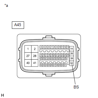
(b) Disconnect the A45 skid control ECU (brake booster with master cylinder assembly) connector.
(c) Check both the connector case and the terminals for deformation and corrosion.
OK:
No deformation or corrosion.
(d) Measure the voltage according to the value(s) in the table below.
Standard Voltage:
| Tester Connection | Condition | Specified Condition |
|---|---|---|
| A45-52 (BS) - Body ground | Always | 11 to 14 V |
| NG |  | REPAIR OR REPLACE HARNESS OR CONNECTOR (BS CIRCUIT) |
|

| 2. | CHECK HARNESS AND CONNECTOR (BRAKE BOOSTER WITH MASTER CYLINDER ASSEMBLY - BRAKE ACTUATOR ASSEMBLY) |
(a) Make sure that there is no looseness at the locking part and the connecting part of the connector.
OK:
The connector is securely connected.
(b) Disconnect the A54 brake actuator assembly connector.
(c) Check both the connector case and the terminals for deformation and corrosion.
OK:
No deformation or corrosion.
(d) Measure the resistance according to the value(s) in the table below.
Standard Resistance:
| Tester Connection | Condition | Specified Condition |
|---|---|---|
| A45-14 (+BS) - A54-5 (+BS) | Always | Below 1 Ω |
| A45-14 (+BS) or A54-5 (+BS) - Body ground | Always | 10 kΩ or higher |
| A45-48 (SFRH) - A54-28 (SFRH) | Always | Below 1 Ω |
| A45-48 (SFRH) or A54-28 (SFRH) - Body ground | Always | 10 kΩ or higher |
| A45-49 (SFLH) - A54-31 (SFLH) | Always | Below 1 Ω |
| A45-49 (SFLH) or A54-31 (SFLH) - Body ground | Always | 10 kΩ or higher |
| A45-50 (SRRH) - A54-30 (SRRH) | Always | Below 1 Ω |
| A45-50 (SRRH) or A54-30 (SRRH) - Body ground | Always | 10 kΩ or higher |
| A45-51 (SRLH) - A54-29 (SRLH) | Always | Below 1 Ω |
| A45-51 (SRLH) or A54-29 (SRLH) - Body ground | Always | 10 kΩ or higher |
| A45-44 (SFRR) - A54-18 (SFRR) | Always | Below 1 Ω |
| A45-44 (SFRR) or A54-18 (SFRR) - Body ground | Always | 10 kΩ or higher |
| A45-45 (SFLR) - A54-15 (SFLR) | Always | Below 1 Ω |
| A45-45 (SFLR) or A54-15 (SFLR) - Body ground | Always | 10 kΩ or higher |
| A45-46 (SRRR) - A54-16 (SRRR) | Always | Below 1 Ω |
| A45-46 (SRRR) or A54-16 (SRRR) - Body ground | Always | 10 kΩ or higher |
| A45-47 (SRLR) - A54-17 (SRLR) | Always | Below 1 Ω |
| A45-47 (SRLR) or A54-17 (SRLR) - Body ground | Always | 10 kΩ or higher |
| NG | | REPAIR OR REPLACE HARNESS OR CONNECTOR |
|
| 3. | RECONFIRM DTC |
(a) Reconnect the A45 skid control ECU (brake booster with master cylinder assembly) connector.
(b) Reconnect the A54 brake actuator assembly connector.
(c) Clear the DTCs.
Click here
(d) Turn the power switch off.
(e) Turn the power switch on (READY).
(f) Perform a road test.
(g) Check if the same DTC is output.
Click here
| Result | Proceed to |
|---|---|
| DTCs C146E and C146F are not output. | A |
| DTCs C146E and/or C146F are output. | B |
HINT:
- If a speed signal of 20 km/h (12 mph) or more is sent to the skid control ECU (brake booster with master cylinder assembly) with the power switch on (IG) and the stop light switch assembly off, the ECU performs self-diagnosis of the motor and solenoid circuits.
- If the normal system code is output (no DTCs are output), slightly jiggle the connectors, wire harness, and fuses of the skid control ECU (brake booster with master cylinder assembly).
- If any DTCs are output while jiggling a connector or wire harness from the brake booster with master cylinder assembly, inspect and repair the connector or wire harness.
- The DTCs were probably output due to a bad connection of the connector terminal.
| A | | USE SIMULATION METHOD TO CHECK |
| B | | REPLACE BRAKE BOOSTER WITH MASTER CYLINDER ASSEMBLY |
READ NEXT:
 Air Bag Circuit (C147D)
DESCRIPTION The skid control ECU (brake booster with master cylinder assembly) receives the secondary collision brake control request signal from the airbag ECU assembly. DTC No. Detection Item
Master Reservoir Level Malfunction (C1202)
DESCRIPTION DTC No. Detection Item INF Code DTC Detection Condition Trouble Area MIL Note C1202 Master Reservoir Level Malfunction 1126 Either of the following is detected:
ECM Communication Circuit (C1203)
DESCRIPTION DTC No. Detection Item INF Code DTC Detection Condition Trouble Area MIL Note C1203 ECM Communication Circuit 1161 Either of the following is detected:
Identifi
SEE MORE:
Installation
INSTALLATION PROCEDURE 1. INSTALL TELEPHONE AND GPS ANTENNA BRACKET 2. INSTALL TELEPHONE AND GPS ANTENNA ASSEMBLY (a) Engage the 6 guides and 2 claws to install the telephone and GPS antenna assembly as shown in the illustration. Install in this Direction 3. INSTALL TELEPHONE AND GPS ANTEN
Fail-safe Chart
FAIL-SAFE CHART PROTECTION FUNCTION (a) The windshield wiper motor assembly operates the following protection functions if it detects an abnormal condition, in order to protect the wiper and washer system. Item Protection Content Conditions to Return to Normal Condition Overheat protectio
