Lexus ES: Components
COMPONENTS
ILLUSTRATION
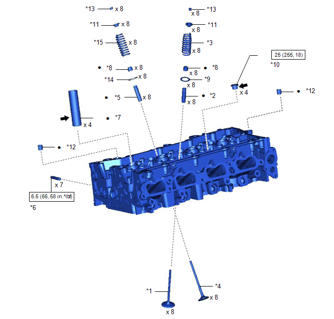
| *1 | INTAKE VALVE | *2 | INTAKE VALVE GUIDE BUSH |
| *3 | INTAKE VALVE COMPRESSION SPRING | *4 | EXHAUST VALVE |
| *5 | EXHAUST VALVE GUIDE BUSH | *6 | STUD BOLT |
| *7 | SPARK PLUG TUBE | *8 | VALVE STEM OIL SEAL |
| *9 | INTAKE VALVE SPRING SEAT | *10 | NO. 1 STRAIGHT SCREW PLUG |
| *11 | VALVE SPRING RETAINER | *12 | RING PIN |
| *13 | VALVE SPRING RETAINER LOCK | *14 | EXHAUST VALVE SPRING SEAT |
| *15 | EXHAUST VALVE COMPRESSION SPRING | - | - |
.png) | N*m (kgf*cm, ft.*lbf): Specified torque | ● | Non-reusable part |
.png) | Adhesive 1324 | ★ | Precoated part |
READ NEXT:
 Disassembly
DISASSEMBLY CAUTION / NOTICE / HINT The necessary procedures (adjustment, calibration, initialization, or registration) that must be performed after parts are removed and installed, or replaced during
Inspection
INSPECTION PROCEDURE 1. INSPECT CYLINDER HEAD SUB-ASSEMBLY (a) Using a precision straightedge and feeler gauge, measure the warpage of the contact surfaces where the cylinder head sub-assembly contact
Replacement
REPLACEMENT PROCEDURE 1. REPLACE INTAKE VALVE GUIDE BUSH (a) Heat the cylinder head sub-assembly to between 80 and 100°C (176 and 212°F). (b) Place the cylinder head sub-assembly on wooden blocks. C
SEE MORE:
Diagnostic Trouble Code Chart
DIAGNOSTIC TROUBLE CODE CHART Active Noise Control System DTC No. Detection Item Link B1AA044 ANC ECU EEPROM Data Memory Failure B1AA187 UART Communication Between ANC and Audio Amplifier Missing Message B1AA296 Front Left Microphone Circuit Component Internal Fail
Front Side Marker Light Circuit
DESCRIPTION When the light control switch is in the tail or head position, the main body ECU (multiplex network body ECU) sends an illumination request signal to the headlight ECU sub-assembly to illuminate the front side marker lights. WIRING DIAGRAM for LED Type Turn Signal Light for Bulb Type Tu
© 2016-2026 Copyright www.lexguide.net
